07/19/2014
The drive has also recently seen some inspiration and progress. Originally I had planned to directly connect the entire drive system with no type of clutch or other disconnect. After realizing the risks involved with everything being steel and very strong, I decided to throw in a slipper clutch from a 1/8 scale vehicle. Larger than 1/8 usually means some sort of high-speed clutch which will not work in this situation. The small slipper is quite common and enjoys support for both technical issues and replacement parts.
I purchased a slipper from Tower and proceeded to adapt it to the truck's needs. I drilled the aluminum spur adapter to accept the slipper's pressure plate, and modified the cone which separates the clutch spring from the spur. This effectively shortened the overall length of the assembly enough to fit a pinion and bearings on the ends. Since I opted for four mounting holes on the chassis plate for drive mounts, I am free to add another support for the forward end of the slipper shaft. Once drawings are completed, I will add photos here.
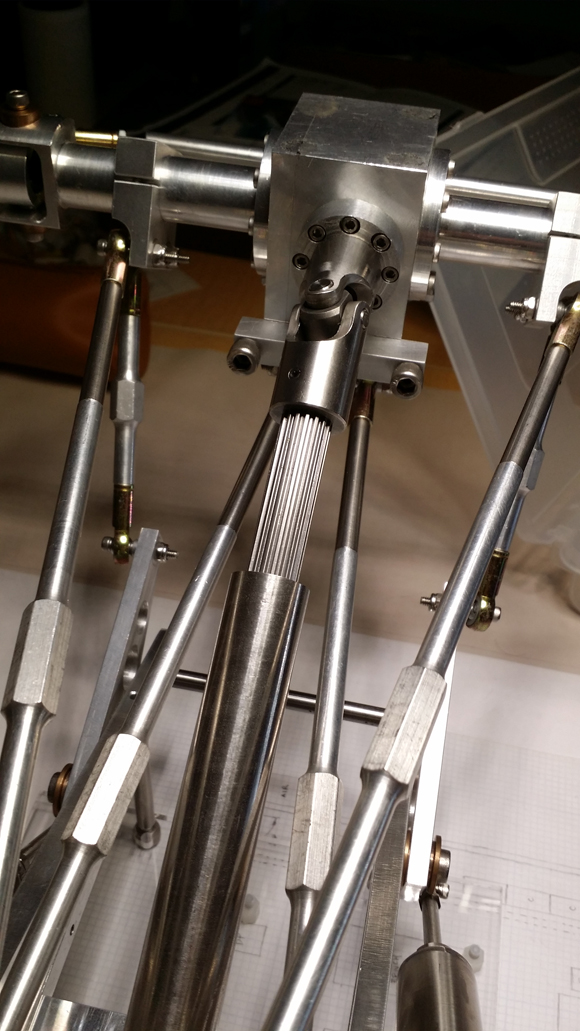
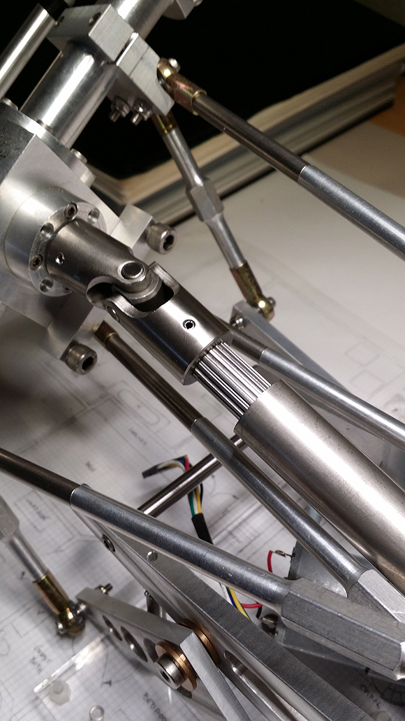
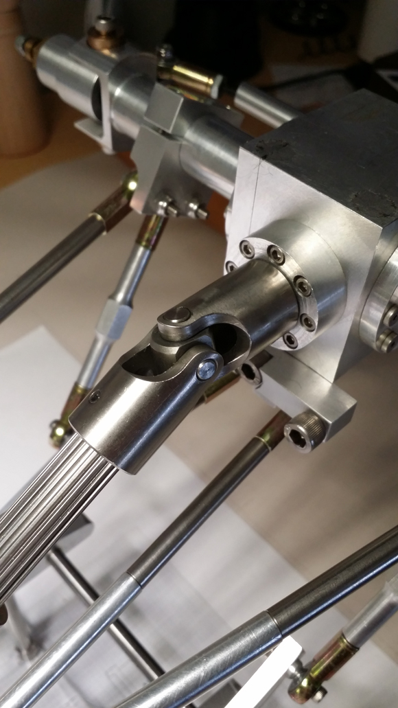
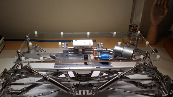
One enormous step recently was the drive shafts themselves. The shafts I fabricated from steel have proven to be wobbly and noisy. Plus, since I used mild steel for all parts of them save for the pins, they have gathered rust. I cannot have this. So, I pointed the browser toward Stock Drive Products and ordered two massive stainless steel telescoping shafts. They have almost three inches of travel and are nearly 13/16" in diameter. Heavy, beautiful, stainless. They are a welcome addition to this monstrosity. In fact, they nearly perfectly match the outer diameter of the shocks, and that makes for a nice bit of symmetry. If I remember correctly, the shafts are 304L stainless and the joints themselves are 416. These are manufactured with a smooth bore at each end so I had to set up and drill each bore for threading. I was a little hesitant to work with them since they are so expensive, but patience and planning paid off. Stainless cone-point set screws capture them to the aluminum bushings. All in all a very nice look.
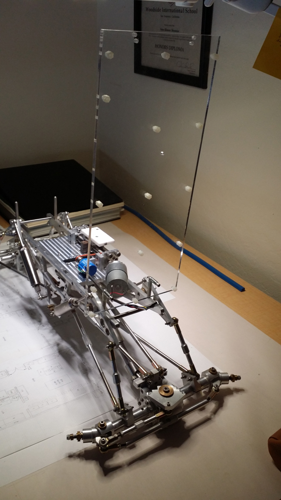
One aspect of this chassis which may not be immediately apparent is the difference in length from the previous photos. In order to adapt the drive shafts, I needed to extend all eight suspension links by another inch over the prior incarnation. This marks the second time the wheelbase has been lengthened from 'stock'. The first was simply to even up the axle length with the frame rails, and that idea grew from a need for symmetry. This new extension became necessary in order to fit the shafts. Another option would have been to use shorter drive shafts but they likely would have appeared too small for the bulk of the chassis.
Now, of course, the suspension geometry is a bit goofed up due to the angled position of the shock links. Thankfully, the thread adapters on the lower shock ends can be spaced slightly off the shock body in order to stretch the length and boost one end of the frame. As for the odd angles created through extending everything, I just don't know what to do.
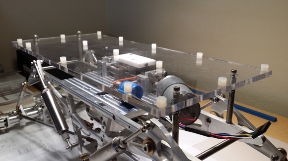
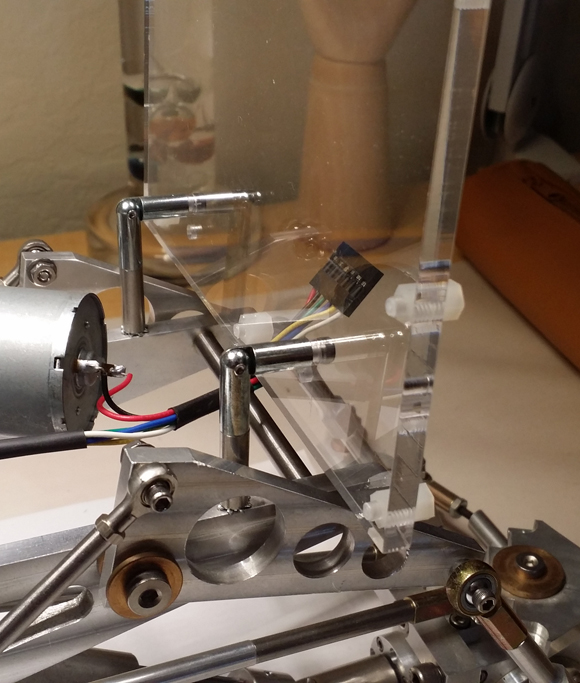
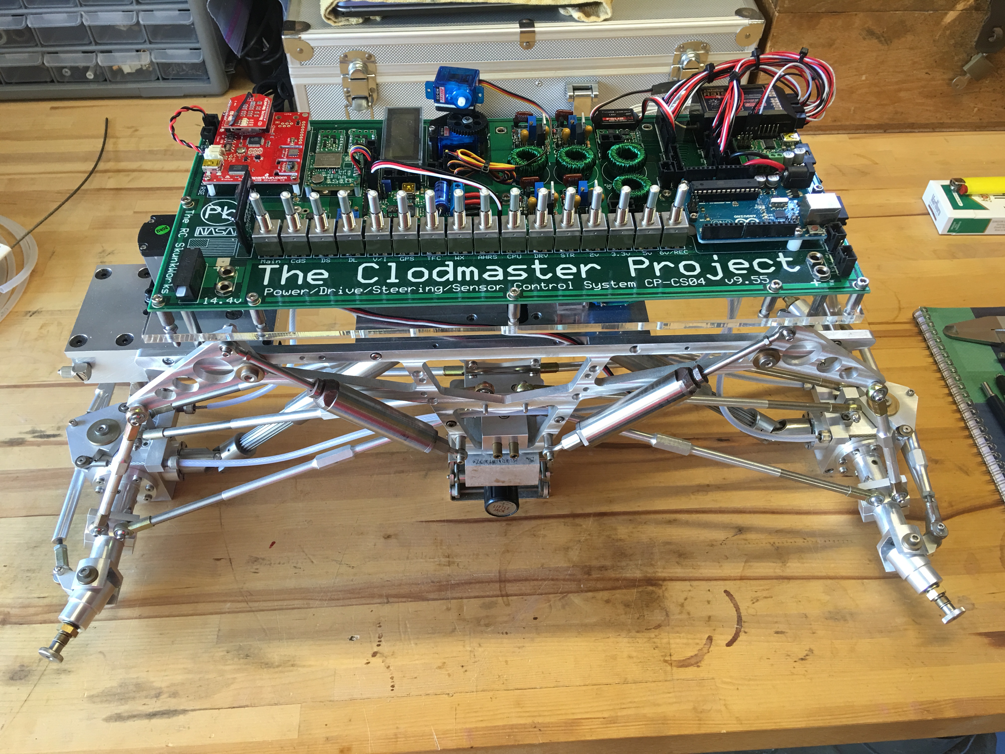
Another recent addition is the acrylic base plate upon which the PC board will mount. I ordered an oversized polished-edge section of plastic from TAP and drilled all of the mounting points for the PC board. I also added two hinged standoffs and two fixed standoffs for mounting the base to the frame rails. Fortunately, the PC board has become large enough to use the old body mounting holes on top of the frame rails. One end has thumb screws so as to be easily removable and allow the entire assembly to be tilted up just beyond 90 degrees. Since the base is clear, the bottom of the PC board will be visible. Also, the calibration adjustment for the LCD volt/ammeter can be easily accessed. Of course, since the board will hinge toward the front of the chassis, I needed to move things around on the PC layout in order to have much of the wiring exit in that direction. The result is the ability to swing the board up without disconnecting any wiring. This should be nice.
The top of the acrylic has been prepped with nylon standoffs for the PC board mounting points. The board will be quite heavy when completely assembled so supports are spaced fairly evenly.
The acrylic is roughly six and a half inches wide, and the PC board is almost a quarter inch narrower. Below, the frame rails sit at just over three inches apart and the axles are twelve inches from spindle to spindle. Why do I point out all these numbers? Well, with things up top coming together, I noticed the chassis seems to look odd because of the narrow frame. I have considered several times over the last few years the idea of expanding the frame width a bit. The logistics of such a change seem simple, and may serve to even out the suspension operation. Right now the axle links are uneven to allow for twisting of the chassis from end to end. The lower links are further apart at the axles than the upper links at the chassis. To ease the explanation, looking from above the links form the shape of a 'W', whereas they technically should be a 'double X'. By spacing the frame rails further apart, the links will even out due to the chassis-end of the upper links being forced outward. I believe this will ease any strain on the mechanics. Fortunately, the top of the frame can be spaced simply by adding longer struts in the form of stainless standoffs. On the downside, the lower suspension mount may be an issue. The entire mount was designed to hold the frame at its current spacing. To expand this would require either a new lower mount or some sort of flange attached to either side. I will experiment and add photos of the results.
07/26/2014
I ran some wire rope for the steering today after letting the system sit for many months. Instead of the past method of four individual segments (two per bellcrank), I opted for two total. Each segment connects one axle. The wire rope is threaded from one clamp on the bellcrank and then through the steering block and back to the same axle. Because of this routing, the carrier no longer has the tension of two cinches per axle. The wire rope travels through the carrier and is cinched twice. I believe because of eliminating two ends being cinched the reliability will increase. We shall see.
08/12/2014
During the last several days I began to notice the chassis was not sitting level at all. There was a difference of almost 3/8" when the height of the frame rails was measured from the floor. I also noticed the angles of the cantilevers were not the same. A simple shim between the shock end and thread adapter seemed to do the trick. At that point I began to see the major change I had caused by extending the wheelbase by two inches. That extension was necessary to fit the larger drive shafts. I spent so much time trying to level the frame rails that I finally noticed how much lower the entire chassis was sitting as compared to years passed. Also (and as I mentioned above), the suspension geometry became goofed up. The four cantilever links were no longer nearly vertical, and the relationship between them and the cantilevers seemed to be softening the springs. On top of this, when one axle is raised to its limit, the drive shaft rubs on the lower link. Sometimes I get these wild ideas to make some sort of dramatic change and when I see the results I realize that the change caused all manner of mechanical mayhem.
All of this became disconcerting so I decided to take the old link extensions that were originally made for the long suspension links and use them to lengthen the cantilever links by an inch each. This worked wonders and now the chassis sits a full inch higher off the floor. Plus, the cantilever links are supporting the suspension much better than before the change. I had no idea simply raising the chassis straight up would have such a great effect on the dynamics of the vehicle's suspension. Of course, by the time the PC board is in place with all of its components, the full height of this vehicle will be upwards of fifteen inches. Yikes. In addition, if I move forward with spacing the frame rails further apart, this may assist with the suspension geometry as well.
08/24/2014
Back a bit I mentioned the slipper assembly and associated mechanics. Since that entry I have received another order from McMaster and now have the necessary hardware to fully design both front and rear slipper mounts. These two machined parts represent the last of the mechanical chassis work and a final end to more than twelve years of design and fabrication.
The front mount will hold the slipper shaft and the rear mount will hold the slipper shaft as well as the motor and its pinion.
01/11/2015
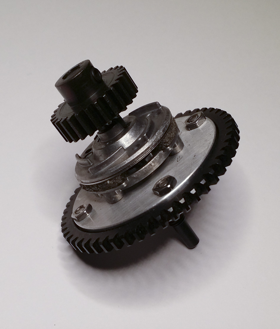
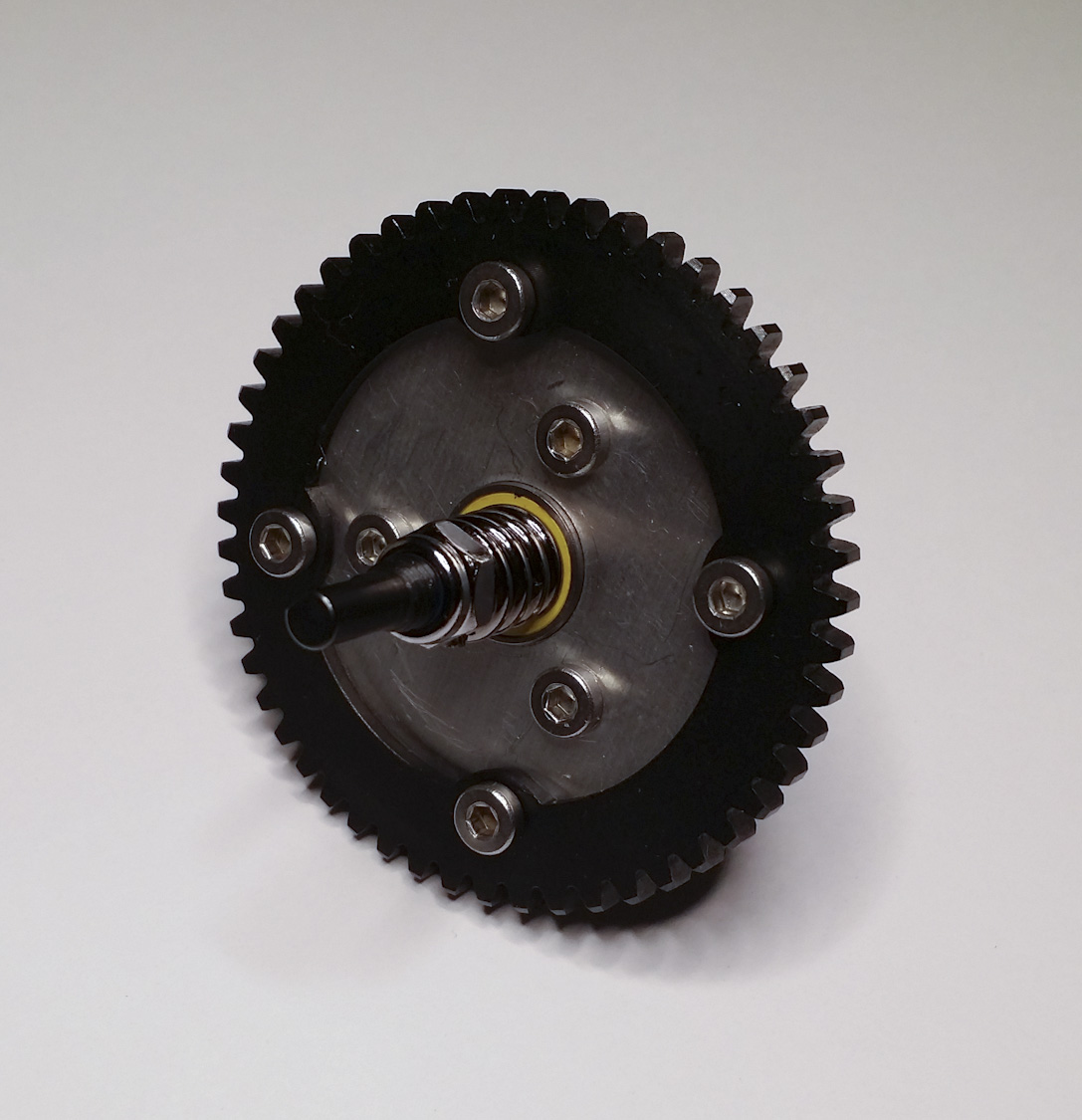
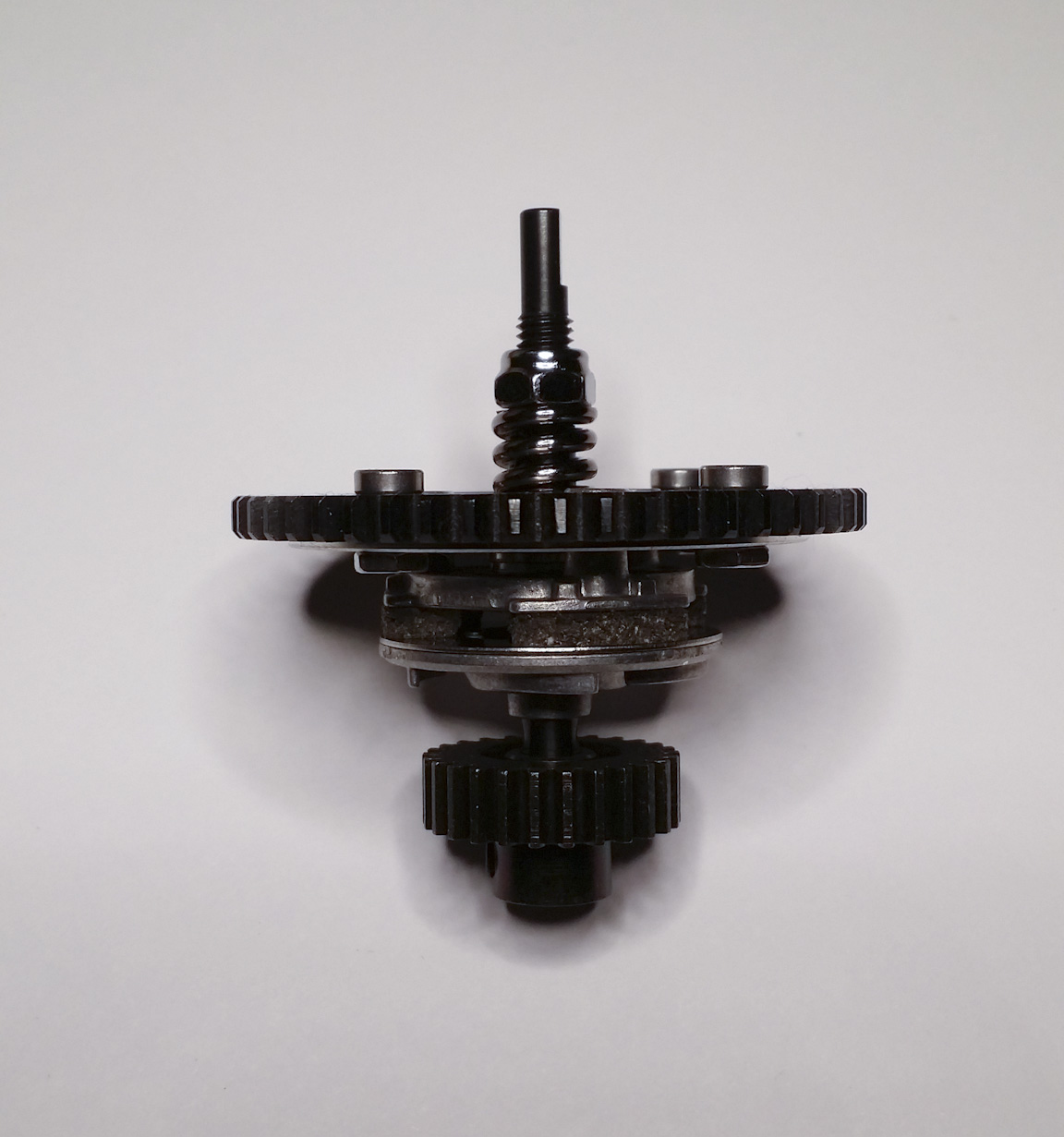
In order to accomplish a slipper assembly that will mesh with the center differential, I needed to modify a Traxxas clutch pressure plate to hold the mating spur gear. This will yield a 1:1 ratio from top to bottom. The motor's pinion is a different pitch which means the mating primary spur needed to match. These are brass gears of the 32p variety. The larger spurs are 20p. The images show an Ofna 20p pinion which was to be the drive gear. I learned that would not work because one of them had to be drilled out to fit the motor shaft and with the equipment I have there was no way to ensure concentricity. Any wobble whatsoever means the gears will wear quickly. So, brass gears save the day as they match the shaft diameters perfectly.
Another issue was to keep any axial play to a minimum. For this I opted for a few nylon spacers and washers which will keep all of the clutch parts from moving along the shaft while spinning as well as maintaining enough space so as to avoid binding near the end bearings. So far, so good. Once I have the mounts designed and double checked, I will order the parts to be made and update further.
09/06/2015
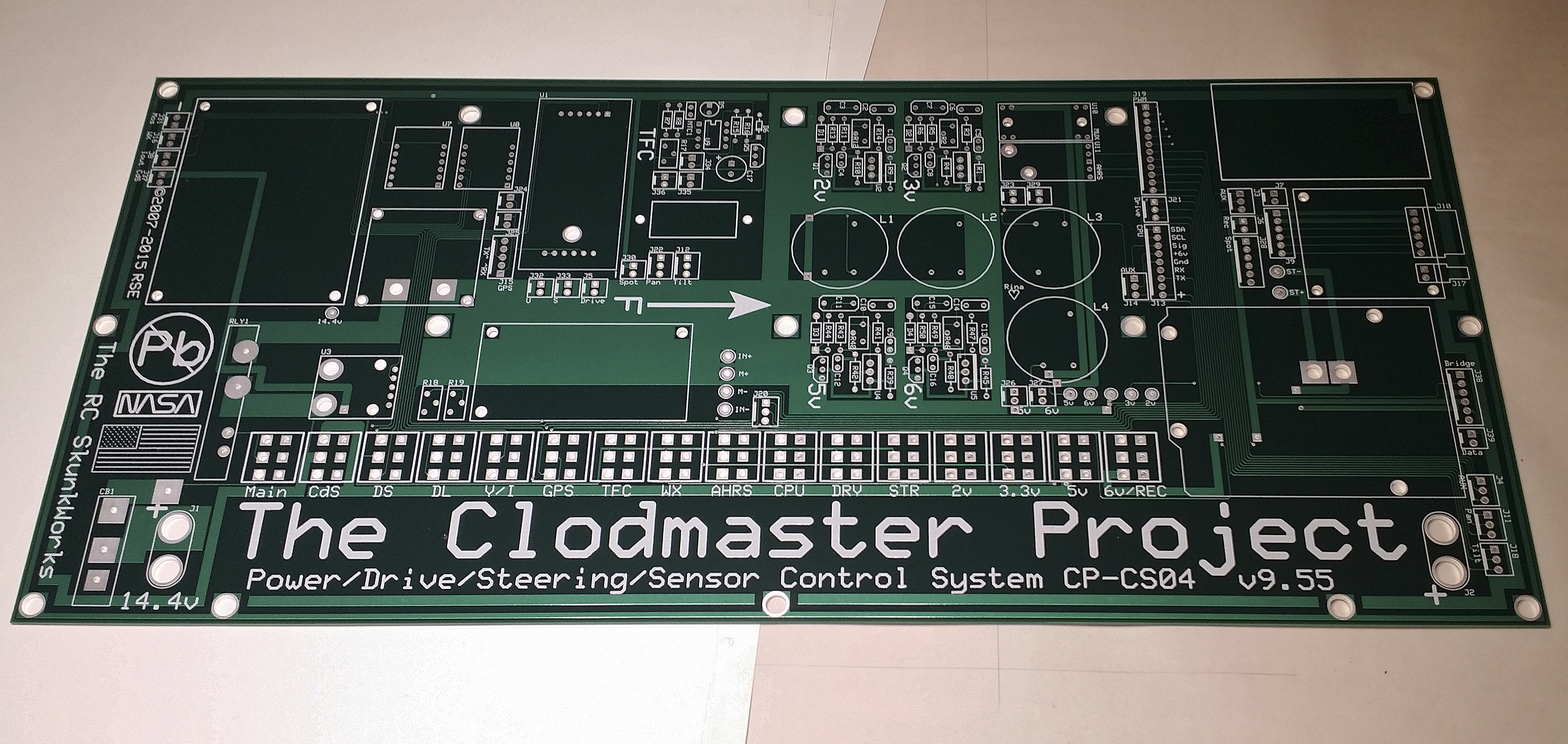
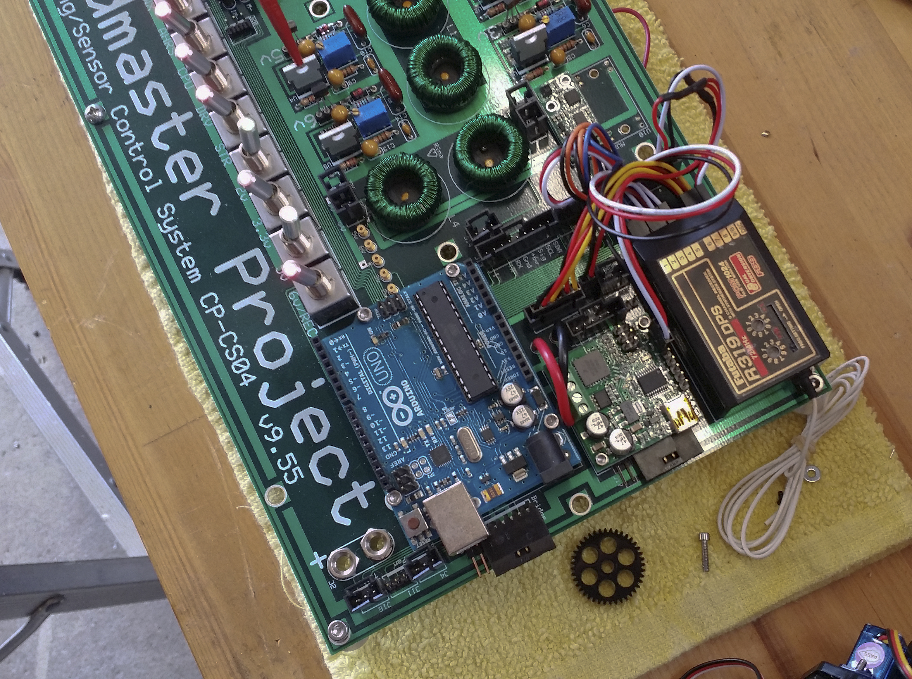
The past month or so has seen tremendous progress on this project. At long last, and after more than eight years of designing, refining, and agonizing over the electronics layout and operation, I ordered the PC boards. That was a huge step toward things coming together on the electronics front. I must say that ExpressPCB does a fantastic job of manufacturing these boards. Every dimension is spot-on and the finish is gorgeous. Solder masking is nearly flawless and protects the copper very well. All of the hole and component locations are within stated tolerance, as well. In short, the board matches my design to a tee.
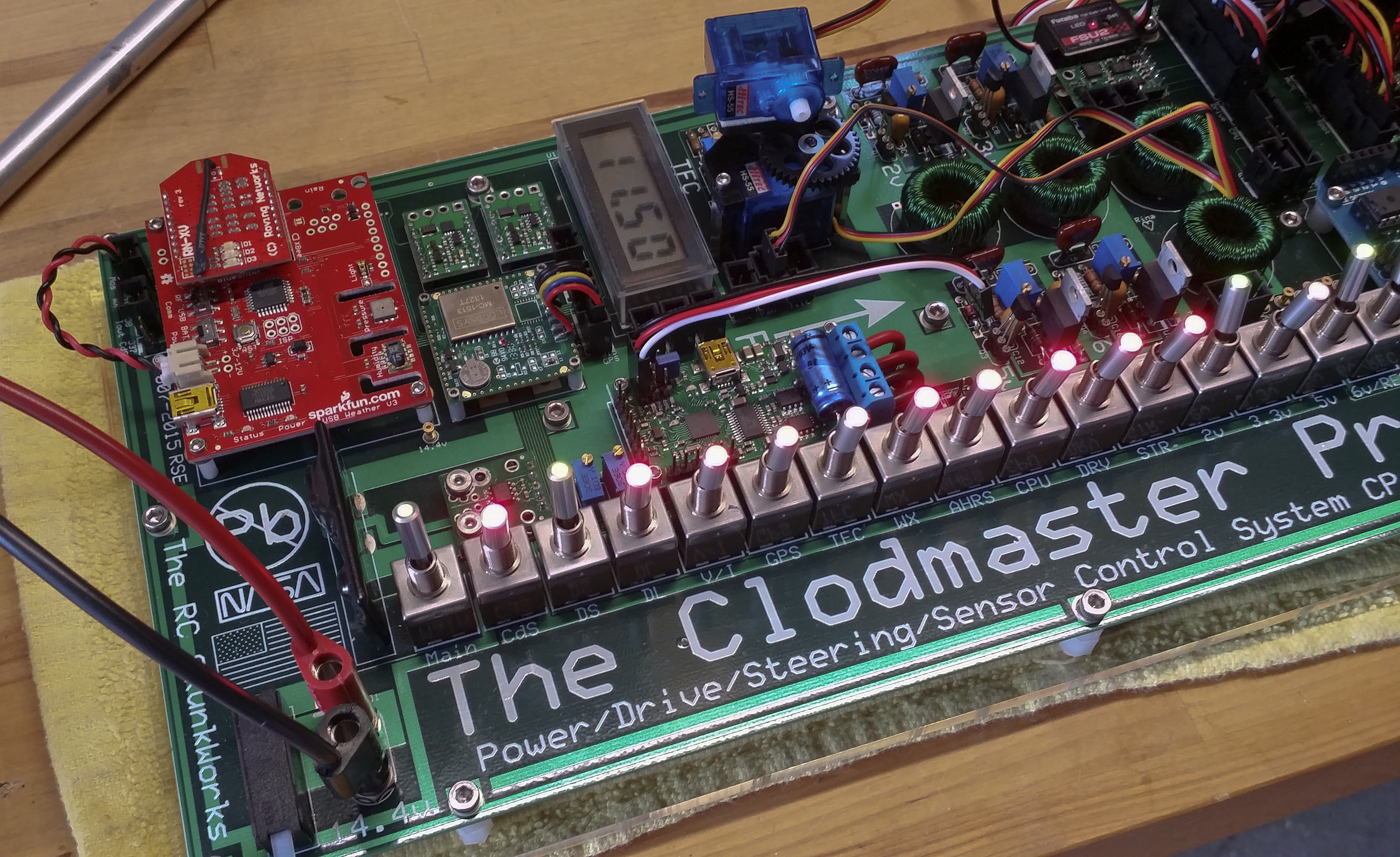
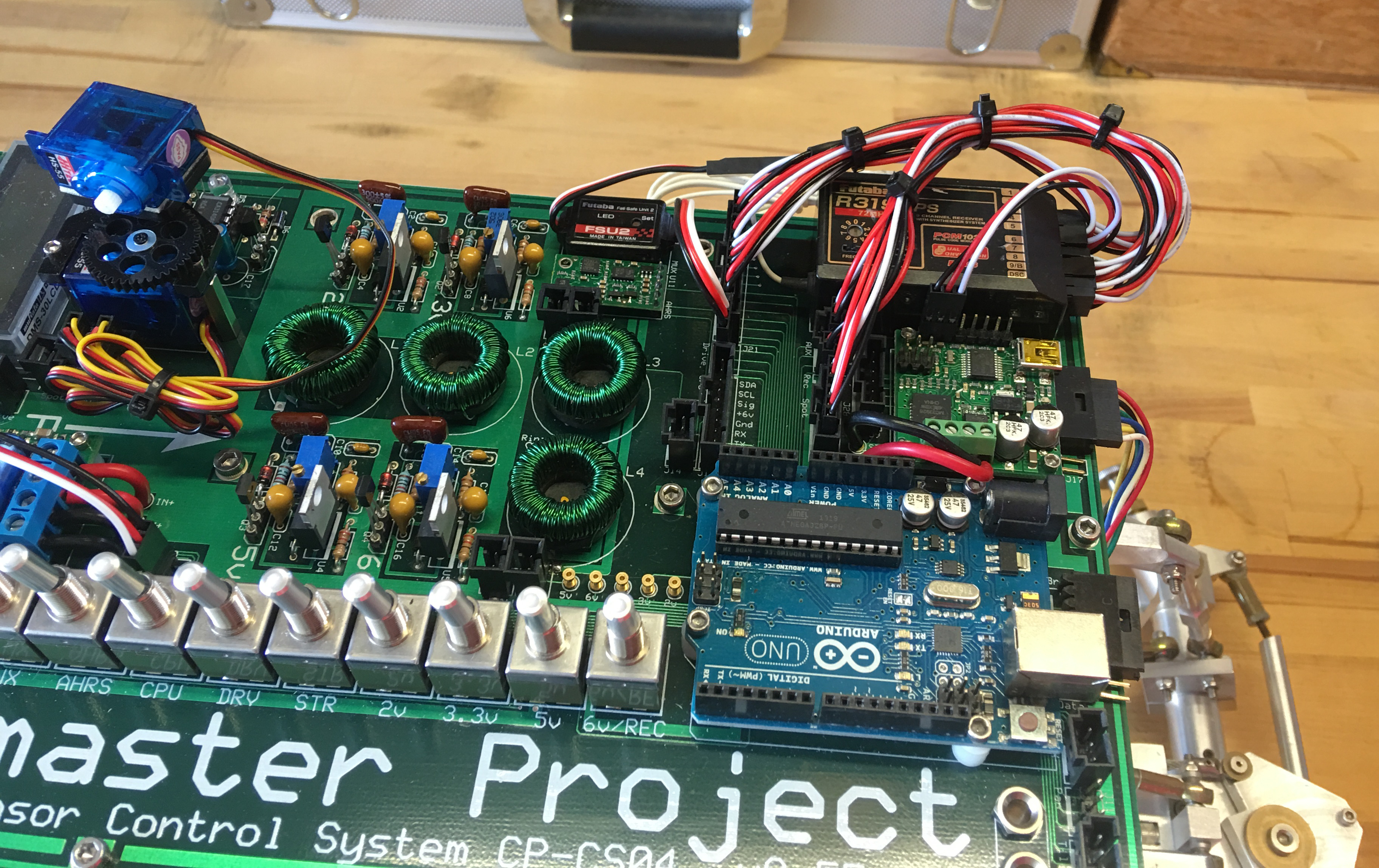
The first step toward operation was to assemble the regulators and run some tests. Everything performed as expected. The solder work has been tedious (mainly due to the fact that I am so picky about the look of things) but nearly complete now. All four regulators work well and hold their voltage levels nicely even during varying the main input voltage. The layout made sense as I tried to move all external connections to the forward end of the board to allow for pivoting up when necessary. The motors and camera pan/tilt connect to the forward end, as well as the bridge and auxiliary receiver outputs.
One issue seems to be signal quality, and this problem may simply be the receiver. It is more than fifteen years old at this point in time and may have degraded over the years. Three of the channels (2, 3 and 8) behave normally for a period and then exhibit erratic behavior through the servos. A few seconds of such and none of the three channels respond to commands from the transmitter. I have yet to find a solution for this and if replacing the receiver becomes necessary it is honestly just a drop in the bucket. I did put the receiver output from channel 3 on the scope to read the pulse width quality and it shows constant voltage on the signal pin and lower-than-expected voltage on the 6-volt pin. I have yet to comprehensively test the other channels in question. They will read very similar, I suspect. Of course, the model has functions for all nine channels on the receiver and anything not operating smoothly will cause me to rethink using 72MHz.
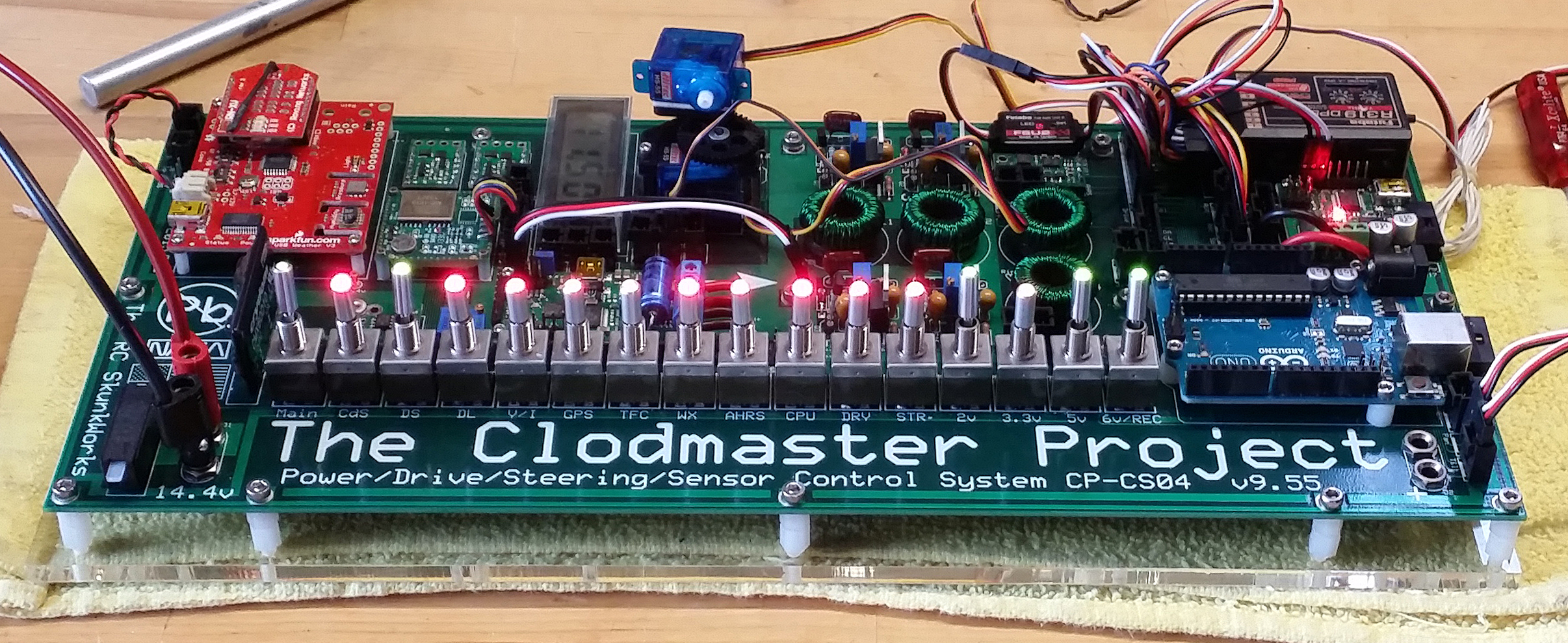
As can be seen above, the board matches previous layout images perfectly. Wiring everything is tough with such narrow spacing and has resulted in a bit of a mess near the receiver and main headers. Over time I will shorten and tie the sections to keep them neat. The coloring of the silkscreen layer is bright enough to read all of the font work down to .050", and the detail is clear throughout. Readability is very important for the smaller lettering, especially for such a large layout.
I am so far very pleased with the look and overall function of the big board. Despite trying to cram so many components into as small a space as possible, working within the board has not been as difficult as I had imagined. The headers do not fit next to each other as I had hoped, but using a few bare headers instead of the shrouded type has made it possible to work with such a compressed design. Trying to picture things on the board before it is manufactured is quite tough. I even laid out some of the sub-boards to ensure the external connections would work. So far, so good. And the spot servos fit neatly without hindering adjustment of the TFC. I may eventually relocate the spot pan/tilt system onto the camera mount in order to free up space on the receiver and open up a few more options as to where the board sits within the roll cage. If so, the board height will shrink a bit which will also help with mounting and body clearance.
08/28/2016
After working out some electronics issues and watching still more develop, I decided to at least clean up the wiring at the receiver end of the board. In order to accomplish a streamlined look, it was necessary to rotate the receiver end-to-end. This alleviated the clearance issue between the output jacks and 12-pin header directly in front. Once it was turned around, I was able to adjust the lead length for each channel and clean the whole mess. The look is much nicer and easier to service.
I also mounted the board to a temporary hinge using standoffs. The board is quite heavy so this will not work as a long term idea. Because of the combined weight of the board and roll cage, I will need to employ a piano hinge and allow everything to swing up toward one side of the truck instead of toward one axle. Still, this idea may require stabilization of some sort.
The cage is more than 30 inches long and holds acrylic body panels for a high-tech look. It also holds the camera mount toward the rear of the roof. The weight and height of all of these parts is pushing me to hinge the board and cage in two different directions -- each side will hold weight so the truck can stay on its tires. Just like the race car drivers say... Keep the painted side up.
The entire board assembly is much heavier than I had originally anticipated due to the many changes in regulator design over all these years. At the outset of the idea, there were three regulators, one each for 5v, 6v, and 9v. These were very simplistic and likely would have drifted under load. Eventually the 9v regulator went away due to eliminating end point limit switches for the steering block. I then added lighted switches for each function which required a 2v section to power the LEDs. Once the 2v was configured, I realized there would need to be strict control of the voltage as well as current so the LED power would not damage the diodes (the switches in question are expensive and protection became necessary). As my crazy ideas for additional functioning modules expanded, the need for a 3.3v supply arose. Now up to four regulators, I decided to use switching supplies to keep the signals clean. Also, the receiver power (6v) needed to be fairly stout for all of the servos. Since I eventually added traces for servo power and pulse width modulation, everything went into the stratosphere with regard to cleanliness. The resulting board is enormous when compared to the first design.
Plus, the servo pulses running along board traces are not without their own issues. And there are more issues...
Upon first powering up the regulators, I noticed the main power switch was not doing much of anything. The voltage reading on the board's display seemed to fluctuate in the neighborhood of 5-600mV when the main was switched on and off. Extensive testing revealed that the solid state relay which controls the 13.8v rail (from which everything is drawn) was not opening when the main was switched off. Apparently there is some bleeding of voltage on the rail which is below the threshold of the relay (~300mV). Suspecting the relay was defective, I quickly replaced it only to find the same result. At that point I began to systematically cover the board with test probes and even drew a huge flowchart in order to diagnose the issue. In the end, I found nothing. All traces test out fine and everything else is operating as it should. So, the relay sits there and flaunts its high price tag in my face day after day. On the upside, there is a thermal breaker upstream of the relay which performs flawlessly.
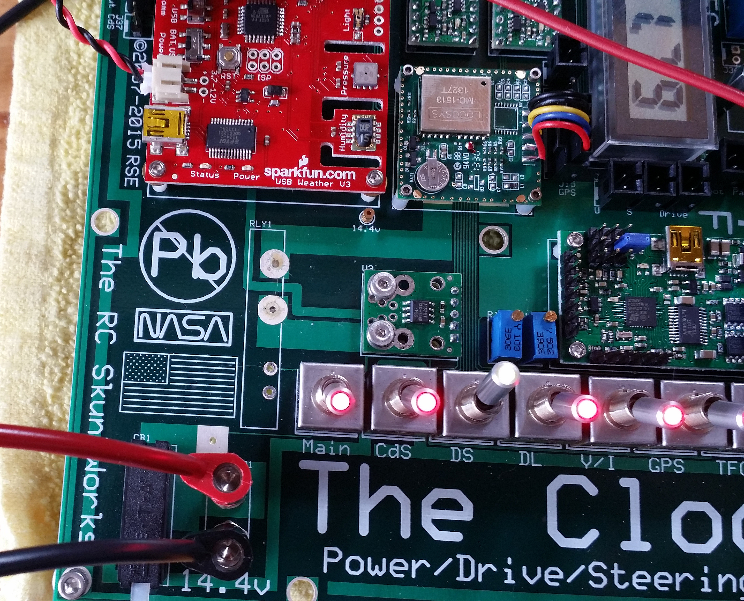
No complex system is without its headaches, right? Ugh. The relay was removed for a time and the photo below shows its footprint.
Also visible in the photo with the missing relay is the SparkFun USB Weather board which was very difficult to locate. Once discontinued, I searched the world and finally found one in Singapore. Whatever the effort, the left end of the board was designed around the size and shape of that component and I just would not have it another way. To the weather board's immediate right is the GPS module and below, the infamous current detector which to this day I am still trying to work with. That board is very flexible with regard to output voltage, and I even went as far as making all of the previously-fixed resistors into trimpots for further adjustment capability. Still, and ever after a year of tweaking all of the trimmers, the current display which should represent the draw of the entire system remains below 100uA. This is unlikely, for sure. Fortunately, I can work with it outside of the remaining parameters. It is only for reference, anyway.
I really went to great lengths and costs to make this system look and work exactly the way in which I had envisioned years ago. So far, the entire picture from the axles to the top of the spot mount is extremely technical, and quite colorful. Of course, this shelf queen will never be dirty. Can you blame me? For Chrissakes, it just went out of control.
Several aspects and systems are as of yet unrealized. For instance, the auxiliary 5v micro-USB input has been removed due to issues related to the regulator, the Arduino inputs are not interfaced with the AHRS, and the 12v switching mosfet seems to be putting out 5v at the header ground when signaled from the transmitter. These problems are small, of course, but the whole system would be much more inspiring if everything worked as designed. Over time I will work with each section as the higher priorities are smoothed out.
09/04/2016
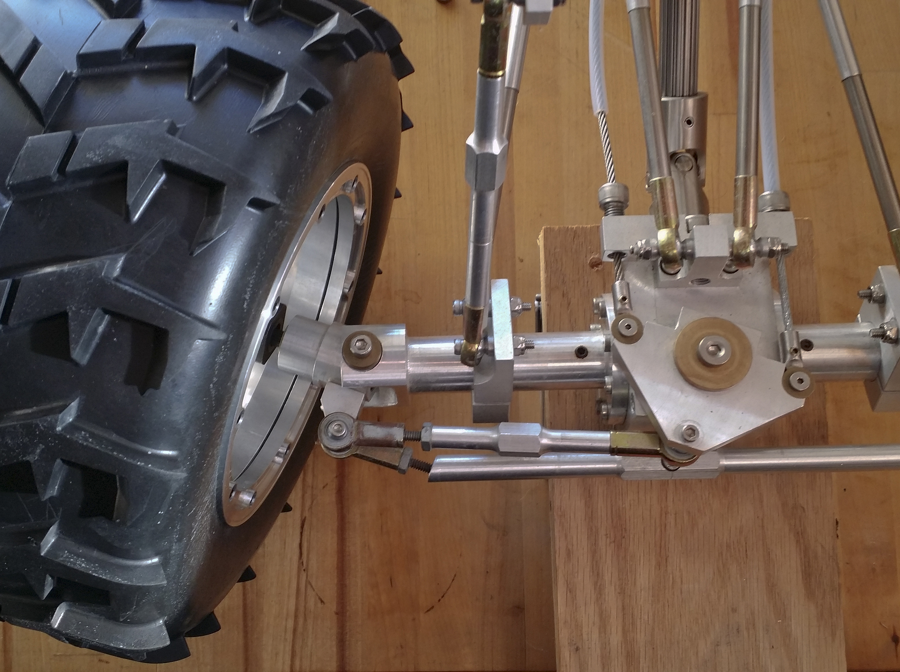
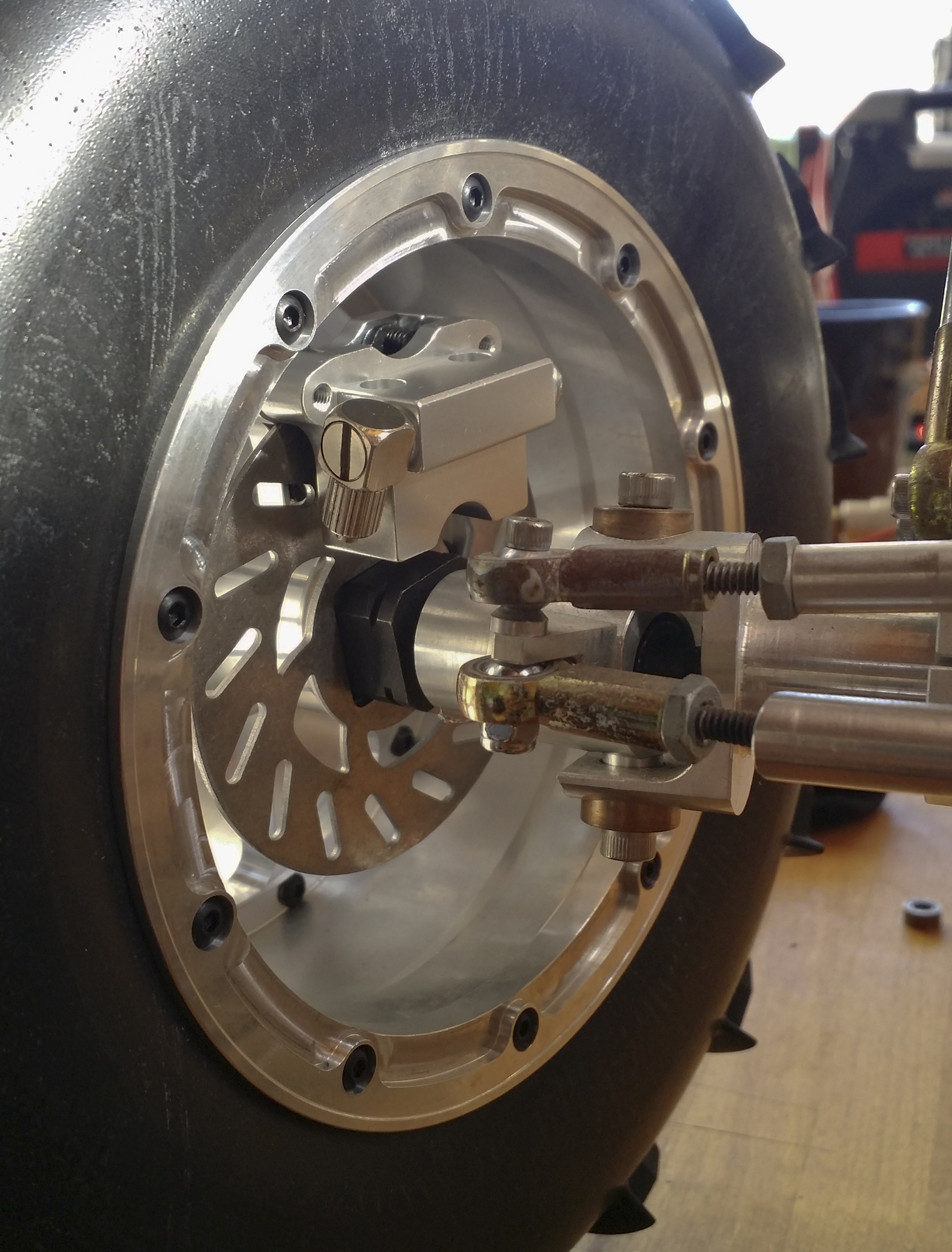
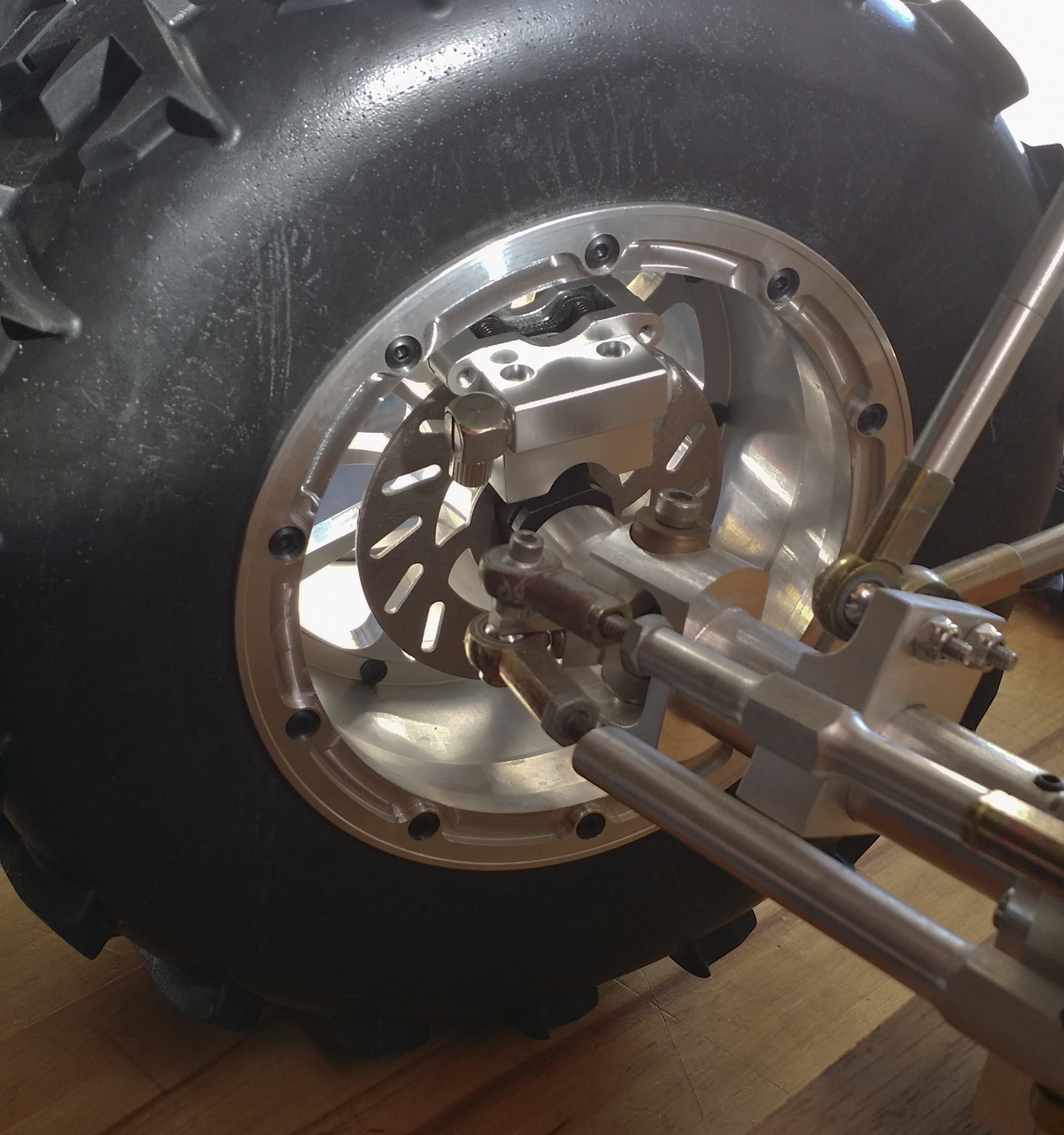
Recent inspiration to operate hydraulic brakes on this crazy vehicle has pushed me to change the hub and wheel style in order to fit brake discs. Since the discs in question mount to a 17mm square, I had to design adapters which will cap the brass hex drives and add a bit of track as well as allowing enough room for the disc and caliper. Also, since the drive style has changed to use the discs, this means new wheels which mount to the same square. Ugh. Out with the smaller beadlocks and in with the huge British wheels and tires which are designed to fit an FG off-road vehicle. This also means once the adapters for the wheels arrive, I still need to design mounts for the calipers at each corner of the vehicle because the truck was not originally designed to have brakes.
This is only about the tenth time I have added something nutty and end up modifying other existing parts. Hence the timeline from 2002.
As can be seen below, the new wheels are a hell of a lot larger than those I had purchased from RC4WD years ago. The original tires were roughly 6.5" tall and the new tires are 8.5" tall. This is quite a difference and brings up the worry of the entire truck being so tall that it will be unstable, even at lower speeds. Once the cage is added, the overall height will be dramatic. Hopefully the ballast of so much unsprung weight will assist in keeping upright.
The photos show a mock up of how the discs and wheels will look once the adapters arrive. I had to adjust the height to allow for the increased tire diameter. One positive is the new wheels have more offset toward the outside so the tires should not interfere with the suspension links. I had this problem after the last lengthening of the wheelbase.
The mounts for the calipers are going to look strange but will also remain rather hidden with the wheels mounted. Since the steering knuckles are rounded, and the calipers are of a different radius, I am going to need to draw them up in a manner which hopefully looks decent. The master cylinder is toward the rear between the frame rails and the fit of that was pure luck. I had no idea of what to expect when I ordered the braking system and the aluminum not only matches the frame, but is nestled between the rails with absolutely no interference with anything.
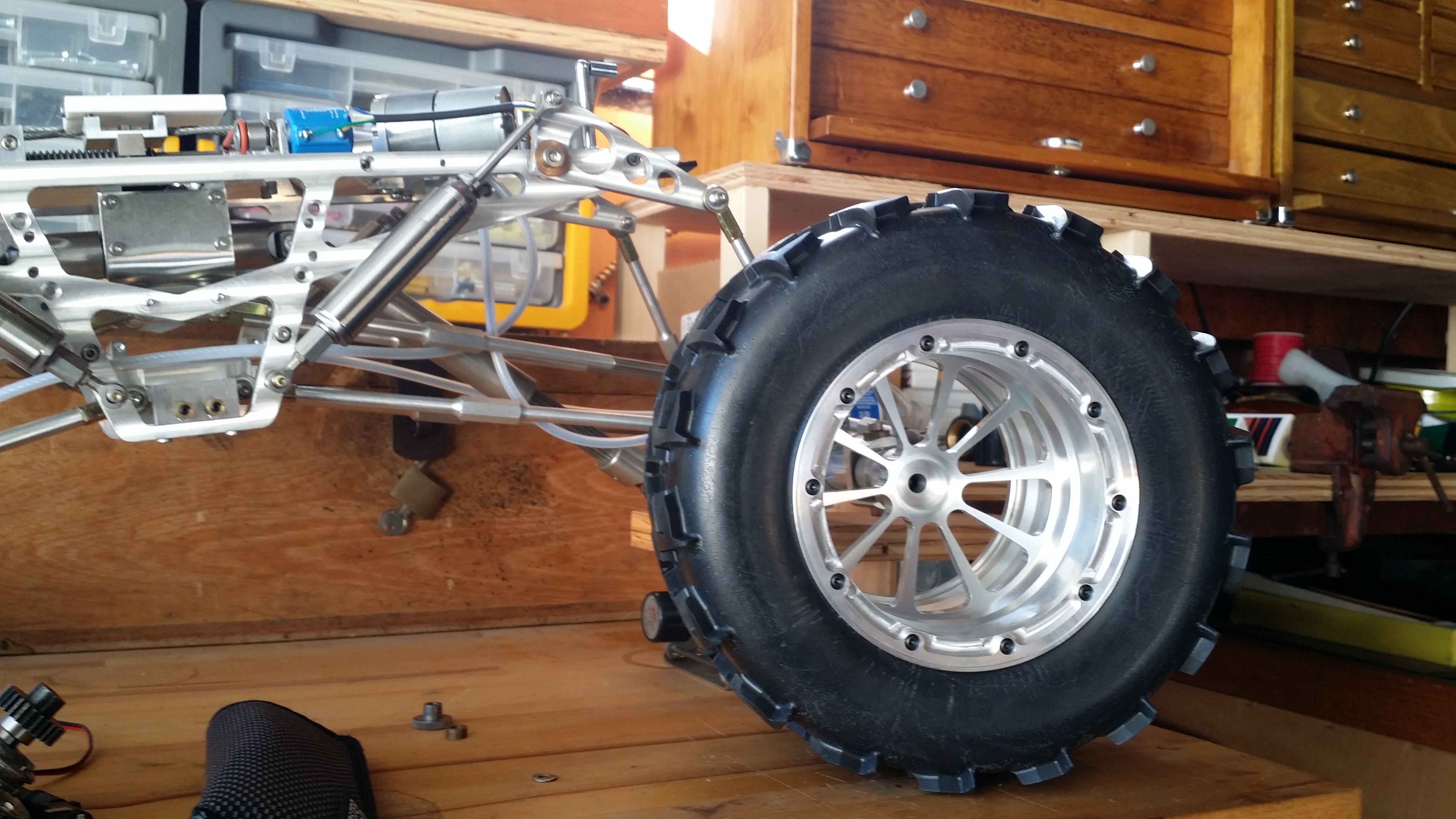
Below is a side view to show the style of the wheels and the fact that the huge diameter is beginning to make the rest of the chassis look rather small. The overall length from tire to tire will be over 29" when mounted.
02/19/2017
Throughout the fall I was able to finalize the designs of both the hub adapters and wheel nuts for the new wheels. Micro Logic did a gorgeous job (as usual) of machining the parts and everything is together. I now have the unenviable task of adapting the calipers to the steering knuckles. Once those are complete and manufactured, I can get the calipers on the truck. The master cylinder is still resting in its temporary location between the rear of the frame rails.
Still upcoming is the damned drive motor and clutch mounts. These are only two parts but the measurements and locations are critical. After mounting the steering feedback potentiometer on the main chassis plate, the original forward clutch mount design had to be modified in order to fit everything cleanly on the plate. Also, the steering cables remain disconnected during other work due to their being in the way. I did mount some of the routing clamps for the steering tubing so once everything for the drive, board, and roll cage are in place, the steering can be assembled without interfering with anything else. The cables will be routed so as to make disassembly easier.
02/25/2023
I dragged out the truck and associated materials some months ago with the intention of updating my design for the motor and clutch mount. After realizing that all of the dimensions were critical, I decided to perform a mock up of the mechanical connections prior to shelling out money to the machine shop. Once the part is made, there is little I can do to make adjustments and/or modifications. Moreover, the machine work is not cheap. So, off to the McMaster site I went for materials and hardware. Once everything arrived, I was able to fabricate a u-shaped mount for the clutch and both pinions, after which I mounted the motor off to one side. The assembly was clamped to the chassis plate for tests and, aside from some tweaking and shimming, the motor drove both axles from my transmitter. The motion was haphazard, though, due to the axles sitting for years without any maintenance. The next step was to pull everything apart and clean, and then I realized that the dogbone/cup alignment was off just enough for the steering to nearly seize the motion when at each lock. I shortened the inner axles and removed redundant bearings and the mechanics ran ten times as smooth. The misalignment was mostly corrected by removing the bearings, thus allowing the dogbone connections to 'float' as I rolled the steering back and forth. The entire affair required days and a lot of patience. At some point during the rebuilding process, I realized the wire rope routing needed to be improved due to stress. Ugh.