03/09/2007
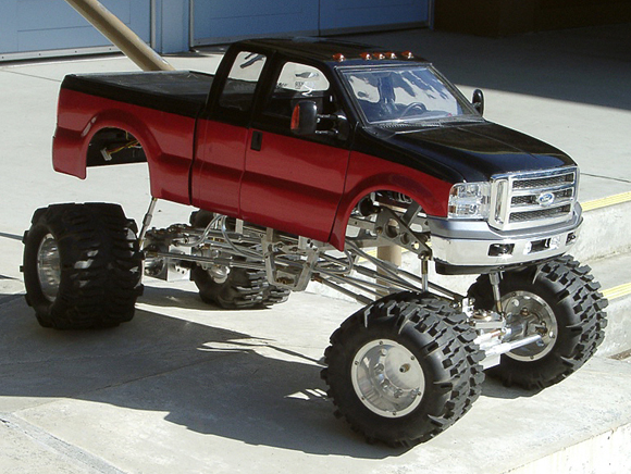
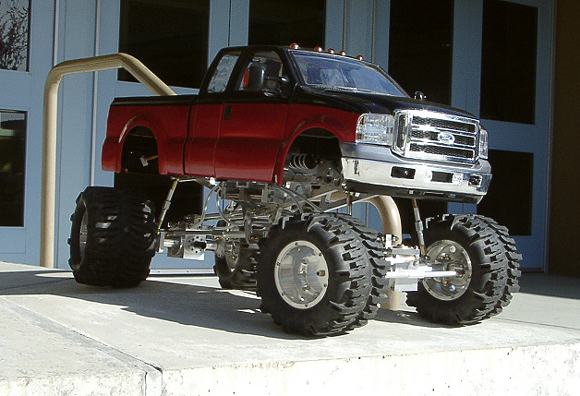
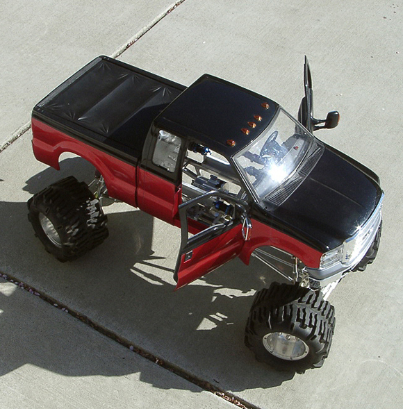
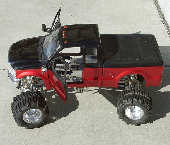
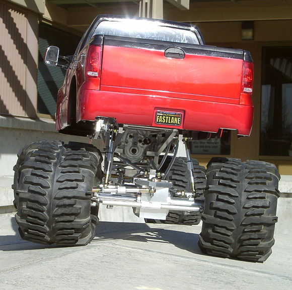
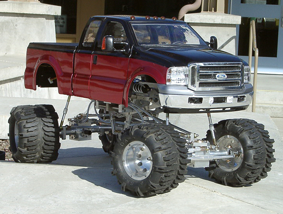
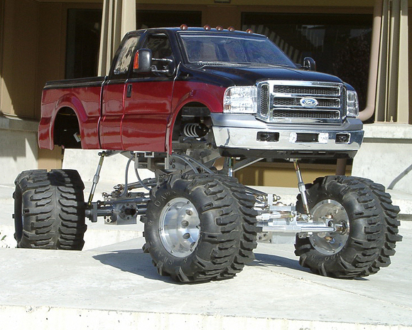
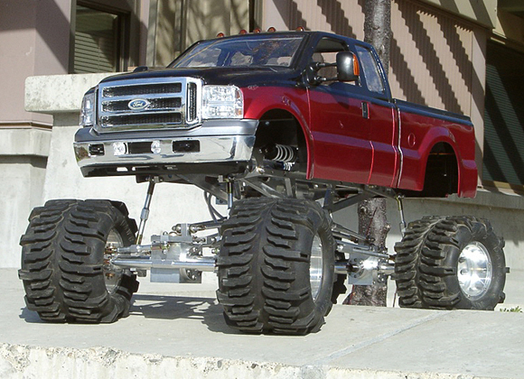
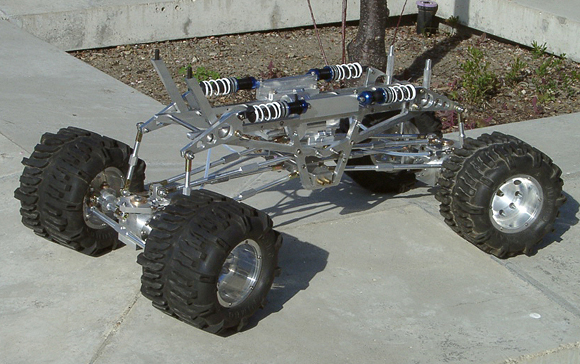
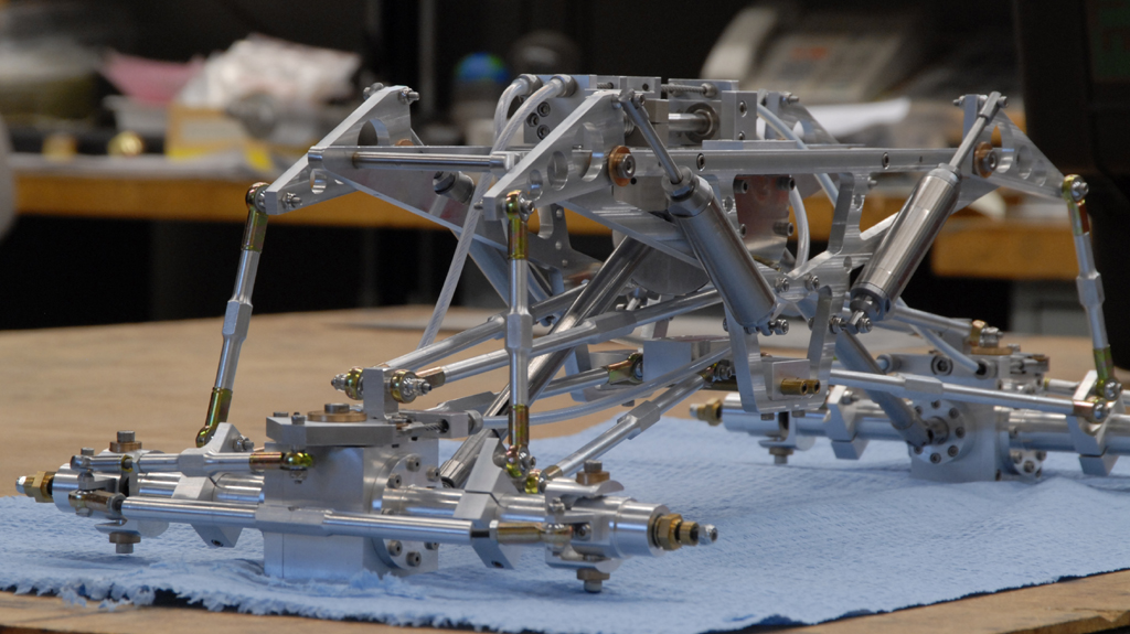
I took some pictures with the truck sitting outside and its body in place. The whole rig seems to be looking decent, despite the tires looking a bit small.
You'll notice that the steering is in the same position in all of these images. Without the stepper motor and associated circuitry, the shaft which drives the linear actuator is difficult to move. I made a tool for positioning the steering system and run some tests, and also ran the steering lock to lock several times with a drill motor and with the tires on the carpet for resistance. After a few runs, one of the cables pulled loose from its clamp and needed to be adjusted. This has been the only weak point located in the system thus far. I'm sure after the truck runs under its own power more limitations will reveal themselves.
As can be seen below, the body is too close to the tires for crawling. These Jumbos are 6.25" tall, and will be replaced by 8.5" Kongs. It is likely I will have to raise the body by at least 2", yielding an overall height of more than 18" and a very tip-prone design. Hopefully, the weight that I am adding below the tops of the frame rails will help keep the CG as low as possible.
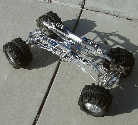
The remainder of the latest shots, and a few with the body removed. Work on the cooling system and dual chain drive continues, and I'll update again with pictures and information about the future of this project.
06/28/2008
I am really slow in updating this site, and I apologize. It was a long Winter and spring.
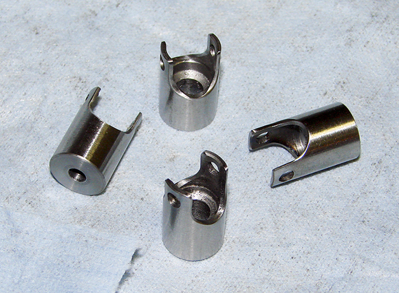
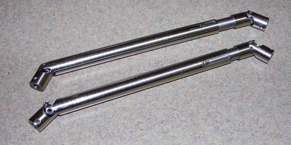
Last December I completed the long-winded design and fabrication of the twin drive shafts. It took a bit of time and Tylenol, but they came out decent. I found that in my quest to create functional shafts, I inadvertently created some good looking parts. In the beginning they were to be polished slightly, but then I realized the ground steel looks just fine against all of the aluminum. Some pictures of machining the shafts:
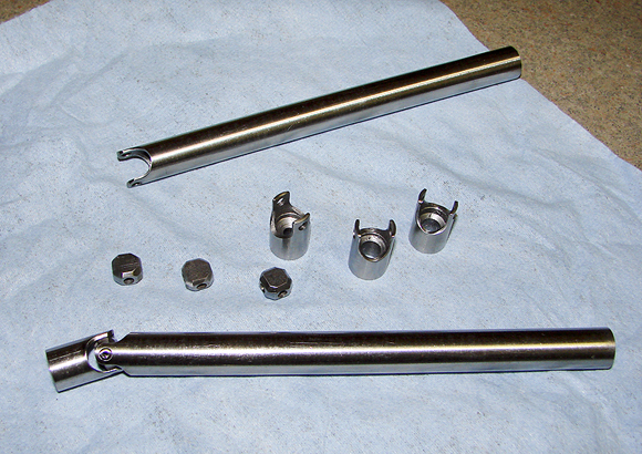
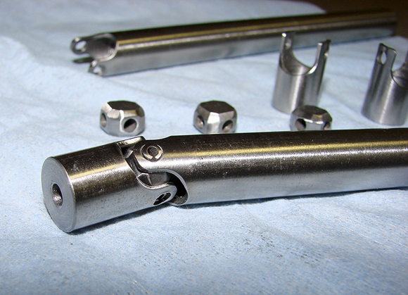
Continued pictures of the drive shafts:
The universals came out pretty decent, and the trunnions also. They really look kind of cool put together, and ended up weighing quite a bit. Overall they are about 9 inches long each, and that's almost all 1/2 inch diameter solid 4340 steel. I'm hoping they don't break> Heh.
[Update, 07/26/2012. The mild steel was a bad idea. As beautiful as these look in the photos, years later they are deeply rusted. I did not protect them at all and the truck sat. I am going to replace them with off-the-shelf telescoping (splined) stainless drive shafts. Yes, I realize that I've made nearly everything here, but I no longer have access to machinery and must resort to buying a few things. The good thing is the stock drive shafts from SDP will fit perfectly. That is incredible luck, to say the least. As usual, there is a huge downside... they are costly (heavy too, but I don't care). Within the next couple of months I am hoping to order them and then fabricate some bushings so they adapt to the input and output shafts on the differentials. One more good thing is the mild steel shafts you see pictured were rather shaky. I don't mean weak or anything, but because of my machining skills the trunnions rattle while turning. That drives me nuts. So, some CNC-made shafts will do the trick.]
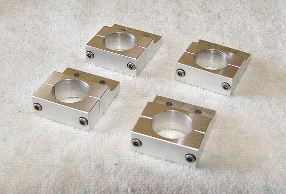
I also replaced the ugly suspension link mounts on the axles. The new design is adjustable and looks worlds better, if you ask me.
The old mounts, looking cheesy (and I can't believe I lived with them for so long!):
And the new:
They are not only better looking, but fully adjustable allowing for improved alignment of the axles. Considering the goofball differential design, there was no previous possibility of changing the angle without machining the suspension links. That was bad planning, but at least it drove me to redesign the mounts.
03/22/2012
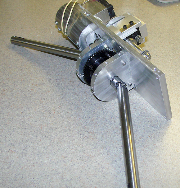
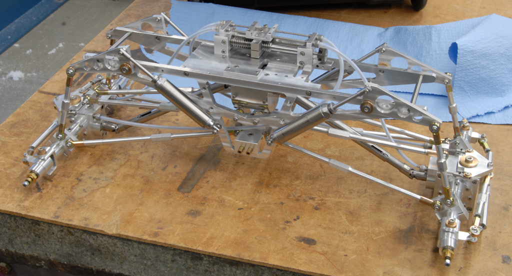
So, after all these years since the last update much has taken place to keep me away from continuing production on this mess. Previously I displayed photos and a bit of description on the drive shafts. Shortly after that period I was able to complete and install them. Too much work! One more shot of the completed shafts mounted to the original motor, transmission, and center differential.
Once those were finished and installed, I decided to continue in the same vein of replacing parts which were purchased with parts I made myself. The next logical steps in this were the shock absorbers and springs. After seeing so many examples of scale coil-over shocks I became enamored with the look of internally sprung suspension. After weeks of design work, I began to gather materials for machining my own stainless versions of these. What a fucking pain. But, as one of my coworkers continued to point out, I made everything else from scratch... why not the shocks? Yeah, thanks. Progress below.
I had a hell of a time deciding upon the overall length and diameter of the shocks, and the travel was a bit of a pain too. In the end, I figured that they needed roughly 1 1/2" of travel and that became the point from which I could calculate the body length. Also, I wanted them to be spaced similar to the original Clodzilla cantilevers. The angle was not terribly important, but the look of the Clodzilla was attractive so I ended up placing the fixed ends part way down the frame rail instead of along the top. Of course, the damned steering rig was mounted off to one side of the chassis on the frame rail and the shock location interfered. Because of this, I was forced to move the steering block up to the top chassis plate. Relocation of the mechanicals for the steering also served to ease the cable tension and the system worked more smoothly. Who knew? Whatever...
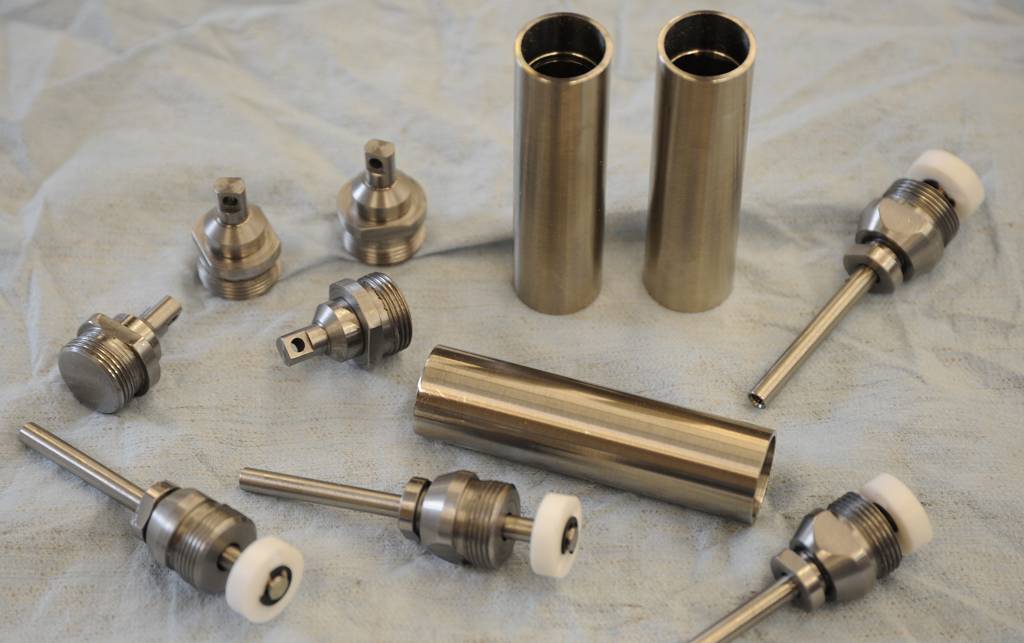
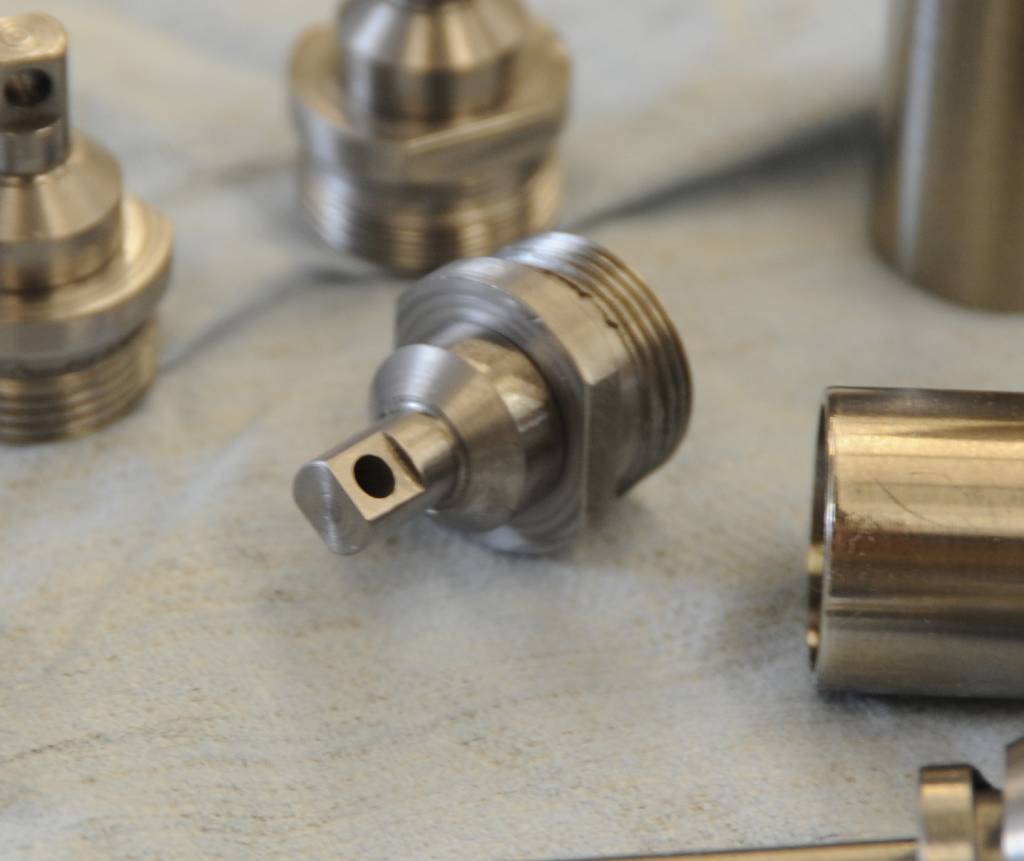
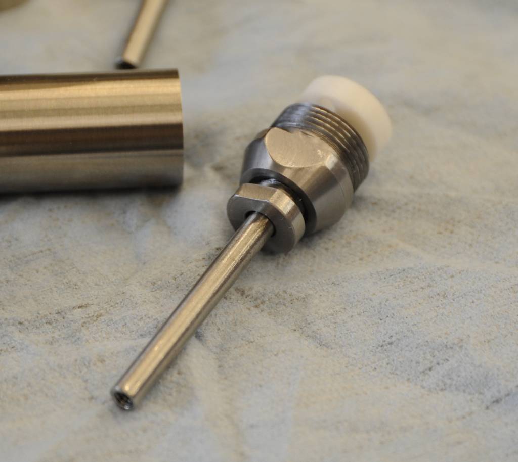
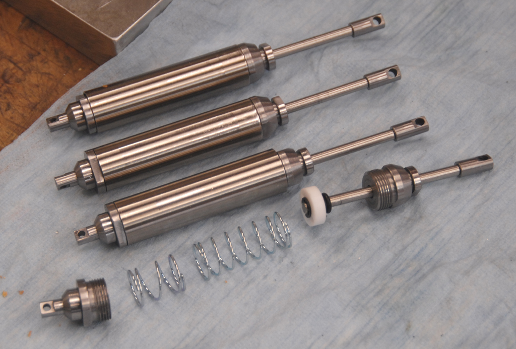
Anyway, here are some photos of the progress on the shocks:
The materials are as follows: Stainless bodies; 4340 steel for the shafts and ends; Teflon packings and pistons; blued-steel clips. I actually opted for sanitary stainless for the body material because of the smooth finish on the inside. That way I avoided any need to polish and the pistons can travel smoothly. As for the springs, well, I am still going over materials and rates. That is a tough call because the truck is not yet to its curb weight. Fortunately, they are easy to change.
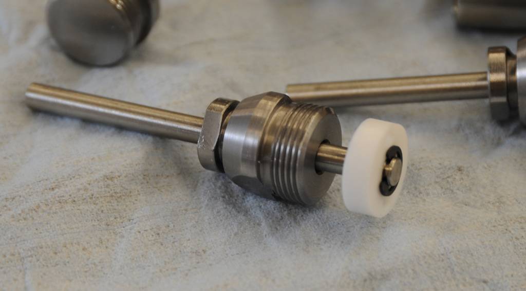
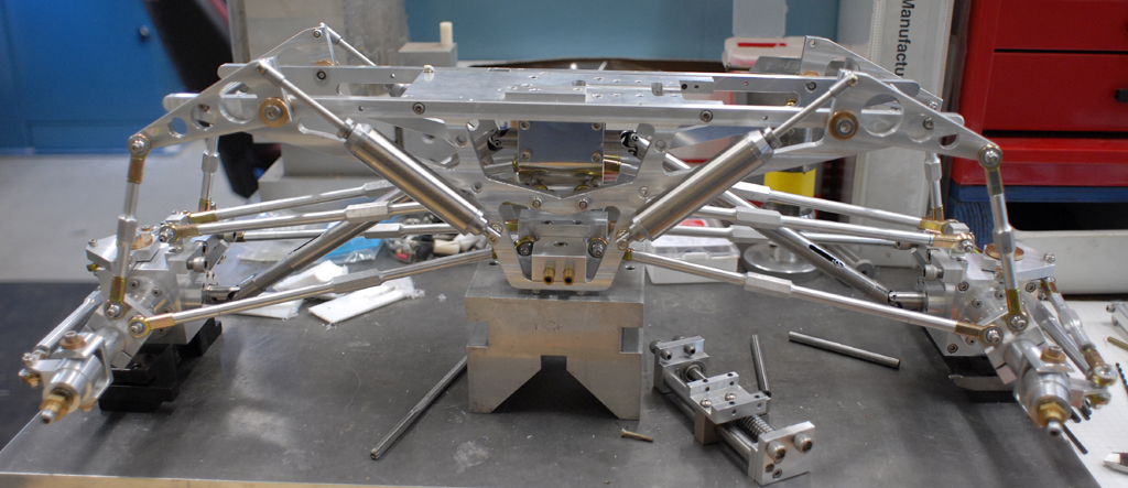
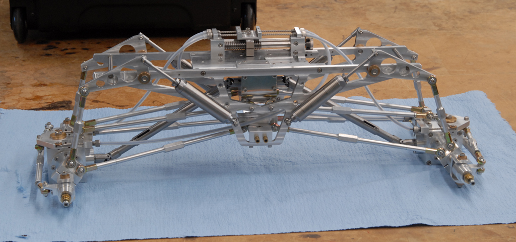
Continued pictures of the shock absorbers and initial mounting.
They do seem to blend well with all of the aluminum and they mimic the original Clodzilla IV setup. I kind of wish I still had that little truck for comparison.
Once the shocks were mounted, I learned (as usual) of the issues with this design.
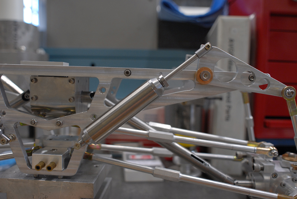
The holes in the ends are very small -- clearance for a #4 screw -- so the mounts are not terribly stout. This is no fun. The upper mounting points on the shock shafts are removable and can be redesigned and made easily. The lower holes, however, are part of the end cap and cannot be switched without machining the entire piece. Why did I do this? Well, I did not wish to see the ends overpower the look of the shafts (they are only .187 inches in diameter) so I made them small, resulting in a tiny mounting hole. As usual, the look of the parts and overall vehicle pushed me to make substandard mounts. Now they need to be re-engineered. The shaft ends are threaded 6-32 which means I can find rod ends to fit. Those are readily available. The lower points are not so simple, though. I will come up with something eventually. There is plenty of time.
On the upside, they do look great. Overall, I am pleased with their size relative to the chassis and they match beautifully. Plus, the steering control is on the top of the chassis and looks much better than off to one side. The side mount always bothered me. The steering motor can now be placed between the frame rails, keeping everything fairly compact.
Beyond the mechanical design and construction, I have spent an inordinate amount of time trying to work out the electronics for actuating the steering system. This has been no easy task thanks to my unorthodox cable idea. The simple fact is the lead screw driving each end of the truck requires in the neighborhood of 7.5 to 8 turns in order to move the steering from lock to lock [please see page 10 for details on this]. Servos that have been modified for continuous rotation are far too slow, considering the quickest only turn a 60-degree arc in 100mSec. I need speeds in the neighborhood of 350-450RPM for direct drive, and something like 2080-3200RPM for a worm-drive unit. Yikes!
Initially I wished to use a stepper motor and controller coupled to a microcontroller. The MC would handle the task of receiving the PWM signal from the RC receiver and determining the calculations for advancing the motor beyond what a servo was capable. Of course, this is no easy task for someone with little or no machine language experience. I experimented with both a Basic Stamp and an Arduino. Both proved easy to work with, however neither processor had a clock speed capable of stepping the motor up to 20kHz. Details... Next page. Let me back up a bit to just after realizing the Basic Stamp was not going to work.
I spoke with a coworker and he had the idea of picking up an inexpensive RC servo to see what I could modify. The servo is very simple... The closed loop system uses a pot geared off the motor to let the little controller know of the shaft position. The radio tells the motor where to go and the differential between the motor's position and where it needs to go is corrected. With 6V or 7.2V systems, the servo moves very quickly. At that point a wonderfully simple idea popped into my head: why not disassemble the servo and put a gear reduction on the pot? It is just a voltage reference. With the pot turning slower than it was designed, the motor would be forced to spin further to arrive where instructed. Great idea, right? No...
An RC servo's power comes from combining a motor with a fair amount of torque with a hell of a reduction gear. Changing the gearing means losing torque, but it would need to be changed so the motor speed can be increased. (This could possibly work with a giant scale servo, and I may still visit that idea.) Soon after coming up with the geared-pot plan, I tossed it. The steering system on this vehicle needs much torque and I don't want to half-ass the thing. I have already spent tons of money trying to find the best method. I must be completely confident that the system will work before moving forward with gearing and mounting the motor.
The Arduino idea was promising, if convoluted. My crazy idea was to use the RC receiver to drive a servo directly connected to a potentiometer which would instruct the Arduino to spin the stepper a predetermined number of steps. This actually worked (and hopefully I can get the little video up here soon) but I found the limiting factor to be the calculation the Arduino was required to complete. As the voltage reference from the pot changed, the Arduino took that number and multiplied it by something like 2050 and then sent information to the stepper controller. This was to cause the motor to step as instructed and the result should have been similar to a servo, just much faster. Because of the lead screw, I needed some decent speed on the motor so that the steering wouldn't take all day to move lock to lock. Now, either my programming or the processor on the Arduino was the issue.
For whatever reason -- and I exhaustively researched this -- the stepper would not turn beyond 100RPM. I was able to tweak the code to cut the speed in half, but nothing I tried would move that motor any faster. Also, the motor speed was constant, meaning no matter how quickly I rotated the pot, the motor would remain steady. The only difference was the number of steps. With an RC receiver and servo, the PWM is relative to the radio's control. When the steering wheel (or stick, as it were) is rotated slowly, the servo does as well. Turn that steering quickly and the servo moves at what seems like lightning speed.
After working with that experiment for several days, I decided to shelf it and look in another direction. That was a bit of a shame because for me, just getting the stepper to turn at all was an accomplishment. I even posted the video on Facebook due to my pride in getting something to work. The system was not what I needed, but I succeeded nonetheless.
Cut to months later, and I switched gears yet again. After further reading about servo motors I believe I have located a controller and motor combination which will work. The controller is programmable via software and can operate independently of any on-board computer. The motor itself has an encoder on its shaft which is designed to communicate position to the controller. I am hoping the software will allow me to program some multiplication for advancing the motor speed beyond the PWM signal of the RC receiver. Also, the motor is geared from the factory to provide plenty of torque and that means it can likely drive the steering lead screw directly. Coupling the motor shaft to the lead screw will be simple.
So, that is where things stand right now. I have some of the equipment required for a test setup, and once I locate a triple-output power supply I can begin to program the controller and run the motor.
To be continued.
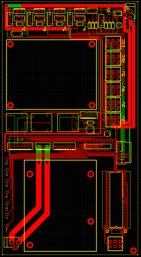
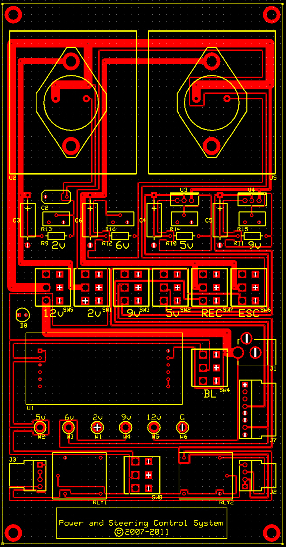
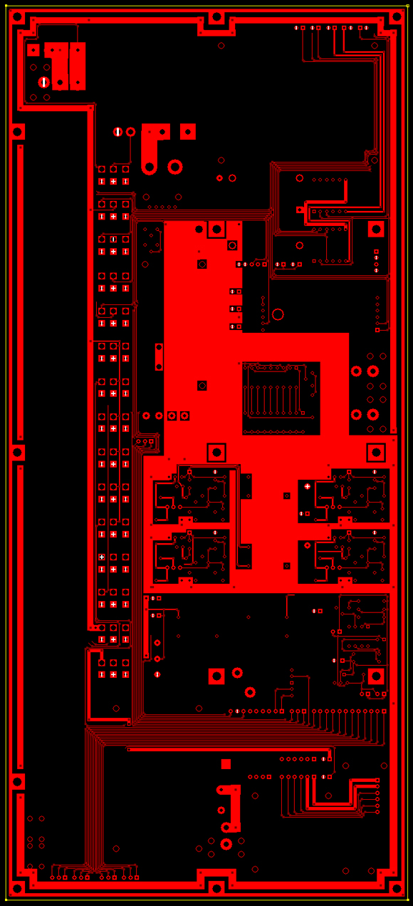
Before going further about the motor and controller I chose for this project, I thought I would include some images of the PC board during design. The first image is the most complex of the designs. The board employed five discrete regulated power supplies, switching for every aspect of the electronics, relays for limiting the steering travel, and monitoring of both incoming voltage and current drawn. This proved unreliable and required a redesign of traces. Originally I had used undersized traces for the two higher-demand circuits and these were then increased dramatically. Also, the regulation for the 2V and 6V circuits had undersized MOSFETs. See image below:
As can be seen when compared to the updated design, the paths were very thin and would have been inadequate for the demand. The redesign also sees elimination of the current monitoring section and on-board processing for the stepper information. This was necessary due to all of my stepper control research heading downhill.
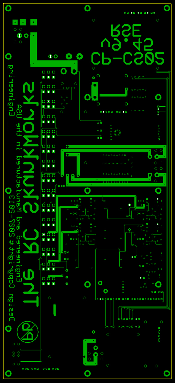
Once I ran into difficulty with the motor, I decided to eliminate any steering control from the board. As a result, the regulation and switching can remain independent of the more complex processes within the steering system. This simplifies the design, saves on cost, and eliminates any possible changes to the board in the future. The newer board is more straightforward:
Pay no attention to my silly engineering logo.
One detail about these images. The upper board shows both red and green traces, as well as the yellow silkscreening. Within the design software, green traces are on the bottom of the board (2-layers). The newer board was designed as a 4-layer without the bottom traces but carrying power and ground planes as the middle layers. I did this for two reasons. First, removing the bottom traces allows for ease of voltage monitoring or troubleshooting; and second, the power and ground planes allow the 2V supply to be removed from the outer layers of the board. This makes the traces MUCH easier for me to follow. I am not an engineer.
Two programs helped greatly with the design of the circuitry. The first is Express Schematic, which has a vast library of components for assembling anything from the simplest circuit to the most complex multi-layer design. The interface is very easy to learn and use. Once the paths are drawn, the schematic can then be linked with a board within the second program, Express PCB. When the two are linked, they work together to minimize errors. This is very handy. Below is a capture of the most elaborate design, which was the plan for the first board above. Keep in mind these designs were first created during 2007.
Note the old "Nitro Crawler" project name in the title block above.
The second image displays the connections for the two monitor displays for voltage and current. The readouts themselves are very nice, as they use large LCD digits on a neutral background. They also employ a soft blue backlight, if desired. I love blue, so I went with it.
The reasoning behind my shelving of this setup was the difficulty in working out details for the current monitor. At first I had thought of finding a successful monitor and then simply adapting it to my needs. However, the circuitry involved did not easily fit with the remaining sections of the power supply. Having a readout of the current being drawn from either the solar cells or batteries is not really necessary anyway, and just serves to use more power and complicate the design. So, I tossed it and stuck with the single display for monitoring the various voltages required. I still need to add switching for the monitor.
The last image is the current design. Simple, yes, but everything required is present and unnecessary items have been removed. This should be cheaper to manufacture as well.
Yes, the second schematic displays yet another name for this project. The name kept changing (I even went through several attempts at humorous acronyms at the request of a coworker), until finally settling upon the 'Clodmaster'. That seems appropriate considering the genesis of this adventure.
Onward...
08/03/2012
After searching, researching, experimenting, and countless hours of pulling out my hair, I located a servo motor controller that is programmable via USB and software. I have yet to power the unit and work with the software, but all of the information about this controller leads me to believe that it will perform the tasks required with a minimum of fuss.
The controller's small size will help to keep the PC board area to a minimum and that translates to lower cost. Plus, this unit requires no external processor to interpret the PWM from the RC receiver. All of the math required to operate the motor at the necessary speeds will be handled by the software. Once the configuration is complete, it is saved as on-board firmware.
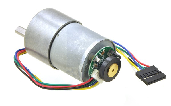
Below we see the gearmotor as provided by Pololu. This motor works directly with the controller above, and has a 64 count-per-revolution encoder on the shaft. Thanks to the gear reduction, this equates to 1200 counts in one rotation of the output shaft. Coupled with the controller, the yield should be an extremely fast, very accurate closed-loop servo. Just what my crazy steering system needs. The cash outlay for both was less than $100. Nice.
Of course, I still have much to work out before operating this system as it will be on the truck. Once the details and testing are complete, I can turn my attention back to the mechanics of coupling the motor shaft to the steering lead screw.
Also, the schematic must continue to evolve in order to adapt to the required voltages. That is the easy part ;-)
08/08/2013
Throughout the past year much has changed with this board design. I have expanded and improved the system greatly, and production is closer than ever. The power supply changes are the most obvious. The old supply had four independently-regulated voltages and that has not changed, however the values and components have changed dramatically. As the system expanded, I realized the need for much more current from the 2V and 6V supplies. To that end, I have upgraded the type of each supply to a switcher. Inductors have been added for smoother operation while under load, and the traces have been expanded to increase current. There is no longer a need for a 9V supply, so that has been tossed in favor of 3.3V for powering some of the smaller boards. Several auxiliary functions have been added and the original microprocessor is gone. Since both the drive and steering motor controllers can be connected directly to the RC receiver there is no need for computer processing. For the task of data collection, there is now a logger with flash memory.
With the increased number of functions, more switches have been added. Independent switching allows for operation of only necessary sections in order to save power. As things stand, there will be lots of batteries just to drive and steer.
The photo below is the top copper layer only. The board is quite complex now so showing more than one layer at a time is necessary. In addition to that, I would like to keep my work a bit of a mystery since I have so much time into it. This has been quite the journey but it is my own.
As can be seen above, the main supply had to be expanded greatly and has become a large plane to ensure there will be enough current for the demand. I have added a solid state relay controlled by the main power switch since the potential amperage has exceeded the capability of my lovely toggle switches. There is also a 10A thermal circuit breaker on the incoming line. That goes without saying.
I did realize at some point that everything was grossly undersized and that prompted such an expansion of the supplies. I have not been terribly worried about the 3.3v and 5v systems because they are logic supplies and the power consumption will be minimal. The 2v is powering as many as 16 20mA LEDs so that rail became perfect for the inner power plane (as discussed previously). The lousy thing is had I planned better in the beginning, the 12v should have been carried by the inner plane and not the 2v. To redesign the system at this point would take a tremendous amount of time. Plus, I really do not want to start over.
Some of the testing that has been done recently has involved the transmitter and receiver. In order to keep the wiring to a minimum, I have run traces from each receiver channel to headers for the camera pan/tilt, headlight switching, steering and drive controllers, mosfets, and auxiliary outputs. Unifying everything onto one board is really nice and serves to avoid the tangles and wire-routing nightmares of which I have dealt with in the past. Of course, as the board becomes more thorough and complex, costs can spiral. In the beginning the entire power supply was less than 2.5 x 4 inches, and now it is 14 x 6.3 with more than 100 components.
Below is the bottom copper layer complete with part number, revision number, and my company logo. I have also included the 'RC Skunkworks' logo to make things interesting. I have been told that logo is silly, but it actually fits this type of project (with a nod to Lockheed for posterity). There is also a stamp for visual confirmation of the lack of lead. That is important.
As displayed previously in these pages, I tried to keep traces off the bottom layer for a more uniform look. The layout became complex enough to require traces on both sides as well as the inner planes. Once I made the decision to run signals and power along the bottom layer, the possibilities expanded greatly.
I have always felt that the logos are important. My name should obviously be there, plus copyright information just in case. My company name shows that this has been (at least somewhat) professional and should serve to help business in the future.
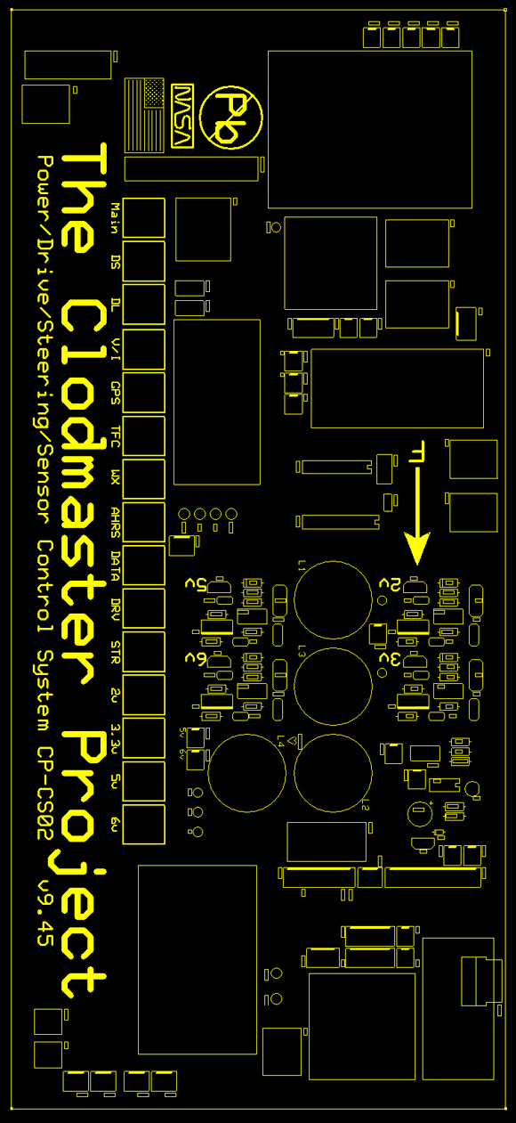
The next image is the silkscreen layer. The production service that ExpressPCB provides is really nice. They put solder masks over both sides and that helps to keep the pads neat during and after assembly. The silkscreen is only available on the top which is good for component identification and labeling. The silkscreen layer is yellow in the software but will be white when manufactured. Also on this layer are outlines for all of the auxiliary boards that will be mounted to the main board. These include both motor controllers, the receiver, AHRS board, weather board, mosfet carriers, current detector, GPS carrier, data logger, toggle switches and the LCD display. The larger boards will be removable. The only difficulty here has been the carrier for the RC receiver. To keep the board size to a minimum, I wanted to employ flathead screws with nuts underneath. That board must be thick enough for the screw heads to be countersunk and still grab enough material for strength. One other possibility is to use the low-head screws (which are now all over the truck) and then just space the receiver above them with foam tape. We shall see which is more feasible.
Of course, the huge Clodmaster Project title is there, along with an American flag, no-lead stamp, and a nod to my previous place of work. Again, the logos might be silly to some, but I am proud of this work and need to display that pride. Plus it may help with promoting the capabilities of RSE.
03/16/2014
Well now, there has been no update on this project for some time. Most of the work quieted for a few months while I attempted to work out the steering motor operation. Finally, and after many years of agonizing over how to get the system to behave as I had envisioned, I made a breakthrough. The issue restricting the motor's number of revolutions as well as proper positioning control was nothing more than the feedback system. Nowhere in the documentation nor the web forums did I find the proper connections for the pot. The manner in which the software sees the 5v reference is quite simple, yet elusive. The reference is actually on the controller and all three terminals from the pot must be connected there in order for it to adjust the voltage accurately. Once I had the connections with the correct placement on the controller, the motor began to position itself according to the input (PWM signal from the receiver). Of course, the rotation of the motor and feedback pot must match or it will rotate continuously.
That hurdle was the single most annoying and frustrating aspect of developing this crazy steering system. Shortly thereafter I wanted to learn if the big gearmotor would actually have enough torque to push and pull as I need. So, back to the garage.
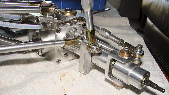
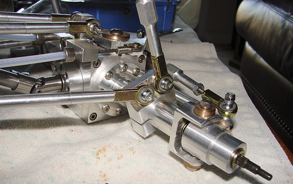
With a bit of measuring, I created a small block of aluminum from my old stock and drill it to accept the motor's mounting bracket. Thanks to SDP-SI I was able to connect the motor to the steering shaft via a 2" universal joint. Their parts are very nice -- great machine work and extremely tight tolerances. Of course, being me, I had to go over it with a fine-tooth comb upon receiving the part to ensure their drawings matched my ridiculous standards for tolerance. Perfect.
I was able to correct the diameter differences between the motor shaft, steering shaft and universal joint with bushing and shim stock, and once everything was aligned the steering worked quite smoothly. The motor seems to have more than enough power to turn my crazy system without flinching.
07/18/2014
...and another long period of time passes.
Soon after running repeated tests on the new steering operation, I decided to oust the old chassis plate and design something less convoluted. Considering all of the changes which took place since first machining the original plate many years ago, the multitude of cuts and holes is not surprising. Measuring everything which needs mounting holes as well as forecasting the primary drive brackets was difficult to say the least. Everything is critical and hole locations would need to be absolute. I slowly drew and edited the new plate over a two month period and then had Emachineshop do the actual fabrication. I must admit their work is impeccable. Upon receiving the plate, I was able to mount everything related to the steering, and the FB pot was then moved off the motor itself and mounted directly upon the plate. I had to fabricate a small angle bracket to hold it, and the connection was moved from the motor shaft to the steering shaft via small pulleys. With this new setup, the relationship between motor and pot is much more stable and accurate. I used a silicone o-ring for the belt itself, and as such it is readily available and easily replaced if necessary. Some tweaking of the input numbers in the software have resulted in smooth operation with decent range.
Such is the present condition of the steering. Right now there are no wire ropes linking the steering block and bellcranks, nor any tubing. Routing must change due to the location of the motor.
On the other half of the mechanical front, the primary drive has progressed, regressed, and progressed yet again. I regret so much back-and-forth but these things take time.